Tout sur les médicaments הכל על תרופות كل شيئ عن الأدوية Все о наркотиках 关于药品的一切 డ్రగ్స్ గురించి అన్ని 마약에 관한 모든 것 Όλα για τα Ναρκωτικά Complete Tracking of Drugs Across the World by Dr Anthony Melvin Crasto, Worldpeacepeaker, worlddrugtracker, PH.D (ICT), MUMBAI, INDIA, Worlddrugtracker, Helping millions, 9 million hits on google on all websites, 2.5 lakh connections on all networks, “ALL FOR DRUGS” CATERS TO EDUCATION GLOBALLY, No commercial exploits are done or advertisements added by me. This is a compilation for educational purposes only. P.S. : The views expressed are my personal and in no-way suggest the views of the professional body or the company that I represent
Purified water has many uses, largely in the production of medications, in science and engineering laboratories and industries, and is produced in a range of purities. It is also used in the commercial beverage industry as the primary ingredient of any given trademarked bottling formula, in order to maintain product consistency. It can be produced on-site for immediate use or purchased in containers. Purified water in colloquial English can also refer to water that has been treated (“rendered potable”) to neutralize, but not necessarily remove contaminants considered harmful to humans or animals.
Water is the most widely used substance, raw material or starting material in the production, processing and formulation of pharmaceutical products. It has unique chemical properties due to its polarity and hydrogen bonds. This means it is able to dissolve, absorb, adsorb or suspend many different compounds. These include contaminants that may represent hazards in themselves or that may be able to react with intended product substances, resulting in hazards to health.
Water is used as ingredient, and solvent in the processing, formulation, and manufacture of pharmaceutical products, active pharmaceutical ingredients (APIs) and intermediates, compendial articles, and analytical reagents. This general information chapter provides additional information about water, its quality attributes that are not included within a water monograph, processing techniques that can be used to improve water quality, and a description of minimum water quality standards that should be considered when selecting a water source.
…………………………………………………………
Pharmaceutical water includes different types of water used in the manufacture of drug products.
THE 8 TYPES OF WATER ARE:
Non-potable
Potable (drinkable) water
USP purified water
USP water for injection (WFI)
USP sterile water for injection
LUSP sterile water for inhalation
USP bacteriostatic water for injection
USP sterile water for irrigation
This ITG will cover the different types of water used in the manufacture of drug products.
THE 8 TYPES OF WATER ARE:
Non-potable
Potable (drinkable) water
USP purified water
USP water for injection (WFI)
USP sterile water for injection
LUSP sterile water for inhalation
USP bacteriostatic water for injection
USP sterile water for irrigation
“Pure water is the world’s first and foremost medicine” – Proverb
Pharmaceutical industry around the globe is witnessing a new paradigm shift in the business model catalyzed by surmounting healthcare cost, patent expiry of blockbuster drugs, uncertain reimbursement scenario, changing healthcare regulations, advent of novel and disruptive technologies, growing customer-consumer engagement, and rising pressure from federal governments and payers to cut down prices.
On account of the aforementioned factors, every pharmaceutical company is trying to save money and preserve their profit margins. These cost-cutting measures are acutely impacting the water for pharmaceutical use market. The major pharmaceutical players are either opting for low cost systems or delaying the purchase of new equipment, which in turn leads to profit erosion for the water technology and equipment manufacturers and suppliers. In order to remain competitive and cement their position in this changing market place, the manufactures are forced to significantly lower down the prices of their offerings.
According to MRFR analysis, the global pharmaceutical market is poised to cross USD 1 trillion mark by 2020. This growth can be attributed to rising demand for pharmaceuticals due to growing base of ageing population, rising prevalence of chronic diseases, and increasing purchasing power of patients particularly in low and mid-income countries. This rise in demand will positively impact the investments for both process water and wastewater treatment systems to increase the manufacturing capacity.
In 2014, the water for pharmaceutical use market, by water treatment systems was USD 720.1 million. The developed economies of the U.S., Europe, and Japan together represents more than 50% of all spending in the overall water for pharmaceutical use market.
Indian pharmaceutical industry is the third largest in the world in terms of volume and the fourteenth largest in terms of value market. Factors such as favorable government policies (such as 100% foreign direct investment (FDI) in the drugs and pharmaceuticals sector and establishment of special economic zones (SEZs) throughout the country) and availability of cheap labor is accelerating the growth momentum of the Indian pharmaceutical industry. In line with these developments, Indian water technology spending market is expected to witness solid double digit growth rate of 13.1% over the next five years. This growth in investments is also fuelled by increase in contract manufacturing and outsourcing of API production.
Water is the most commonly used component in pharmaceutical industry. Water finds its application as a raw material and solvent in the manufacturing, formulation, and processing of pharmaceutical products, active pharmaceutical ingredients (APIs), intermediates, and analytical reagents.
Many different grades of waters are used for pharmaceutical applications. Grades of water quality required depends on the route of administration of the dosage form. These waters can be segmented into two categories:
Bulk water – produced on-site where they are used
Packaged water – produced, packaged, and sterilized to preserve the microbial quality throughout their packaged shelf life
There are several types of packaged water based on applications, packaging limitations, and other quality parameters. The quality control of water, in particular, the microbiological quality, is a major area of concern for the industry and hence, the market players allocates considerable resource in the development and maintenance of water purification and validation systems.
Types of Water for Pharmaceutical Use:
Portable Water: also referred as drinking water. Portable water must comply with the quality standards of either the National Primary Drinking Water Regulations (NPDWR), or the drinking water regulations of the European Union or Japan, or the WHO Drinking Water Guidelines. Portable water can be used in the early stages of cleaning pharmaceutical manufacturing equipment and product-contact components. It is the minimum quality of water that should be used for the preparation of drug substances and other bulk pharmaceutical ingredients. Treatment of drinking water includes desalinization, softening, removal of specific ions, particle reduction and antimicrobial treatment
Purified Water: majorly used as an excipient for the production of non-parenteral preparations and in other applications like cleaning of equipment and product-contact components. Purified water must fulfil the requirements of ionic and organic chemical purity and must be protected from microbial contaminants. The feed water for the production of purified water is portable water. Purified water is mostly produced by ion exchange, reverse osmosis (RO), ultrafiltration or electro deionization processes and distillation
Highly Purified Water (HPW): prepared from portable water. Highly purified water is a unique specification for water as per the European Pharmacopoeia. It must meet the same quality standard as the water for injections (WFI). HPW is produced by double-pass reverse osmosis coupled with ultrafiltration or any other appropriate qualified purification technique or sequence of techniques
……………………..
Water for Injection (WFI): WFI is utilized as an excipient for the production of parenteral and other preparations and for cleaning of equipment and parenteral product-contact components. WFI is non sterile water and is not a final dosage form. It is an intermediate bulk product. Water for injections is prepared from drinking-water (after further treatment) or purified water. WFI adheres with test for purified water with additional requirements for bacterial endotoxins (not more than 0.25 IU of endotoxin/ml), conductivity & total organic carbon
Water for Hemodialysis: is predominantly used for dilution of hemodialysis concentrate solutions. It is produced and used on-site from EPA drinking water which is further purified to reduce chemical and microbiological contaminants. Water for hemodialysis contains no added antimicrobials and is not intended for injection
Sterile Water for Injection (SWFI): is water for injection packaged and rendered sterile. It is used for extemporaneous prescription compounding and as a diluent for parenteral preparations. Sterile water for injection is packaged in single-dose containers not larger than 1L in size
Bacteriostatic Water for Injection: is sterile water for injection with one or more suitable antimicrobial preservatives. It is used as a diluent in the preparation of parenteral products, mostly for multi-dose products that require repeated content withdrawals. It can be packaged in single-dose or multiple-dose containers not larger than 30 mL
Sterile Water for Irrigation: is water for injection packaged and sterilized in single-dose containers not larger than 1L in size which allows rapid delivery of its contents
Sterile Water for Inhalation: is water for injection packaged and sterile for use in inhalators and in the preparation of inhalation solutions. It carries a less stringent specification for bacterial endotoxins than sterile water for injection and hence, is not suitable for parenteral applications
Regulatory Landscape:
Water used in the manufacturing of drug substances or as source or feed water for the composition of the different types of purified waters must adhere to the requirements of the National Primary Drinking Water Regulations (NPDWR) (40 CFR 141) issued by the U.S. Environmental Protection Agency (EPA) or the drinking water regulations of the European Union or Japan, or the world health Organization (WHO) drinking water guidelines in order to meet minimal chemical and microbiological quality standards.
Quality of Water for Pharmaceutical Use:
Validation of water purification, storage, and distribution systems are an elemental part of good manufacturing practice (GMP) and form a basic part of the GMP inspection. The grade of water used in manufacturing of pharmaceutical substances should take into account of the nature and application of the finished products and the stage at which the water is used.
Conclusion:
The production and validation process of water for pharmaceutical use has under gone a tremendous degree of evolution over the time, with many upgradations in quality parameters and production methods. Non-chemical processes and automation are becoming the order of the day. These trends are expected to continue in the near future which will unfold significant growth outlook for this market.
The USP designation means that the water is the subject of an official monograph in the current US PHARMACOPEIA with various specifications for each type. The latter 4 waters are “finished” products that are packaged and labeled as such and need not be of concern during an inspection outside of plants which actually produce these products.
The USP purified water and the USP WFI on the other hand are components or “ingredient materials” as they are termed by the USP, intended to be used in the production of drug products.
But what about potable water as a component? Is it required to undergo routine sampling and testing before use in production? According to the preamble to the Current Good Manufacturing Practice regulations (CGMPs), no acceptance testing is required for potable water unless it is obtained from sources that do not control water quality to Environmental Protection Agency (EPA) standards. It is important to know that potable water may not be used to prepare USP dosage form drug products or for laboratory reagents to test solutions. However, potable water may be used to manufacture drug substances (also known as bulk drugs or bulk pharmaceutical chemicals).
During your inspection, determine the source of the water used for wet granulations or for any aqueous liquid preparations as well as for the laboratory. It should be of USP purified water quality both chemically and microbiologically.
Is non-potable water a concern during drug inspections? It may be present in a plant in the boiler feed water, cooling water for the air conditioning or the fire-sprinkler systems. Look carefully for any cross-connections to the potable water supply. Non-potable water supply lines should be clearly marked as such, especially when adjacent to potable water supply connections.
WATER PRODUCTION SOURCES
The USP defines acceptable means of producing the various types of component waters. USP WFI may be made only by distillation or reverse osmosis.
Potable water is obtained primarily from municipal water systems but may also be drawn from wells, rivers, or ponds.
SOURCES OF WATER CONTAMINATION
Piping system defects may cause contamination of clean incoming water. Because of this possibility, point-of-use sampling is indicated, that is, drawing the water sample after it has passed through the piping system.
Microbial contamination of oral liquid and topical drug products continues to be a significant problem, and is usually rooted in the use of contaminated water. Because of the potential health risks involved with the use of contaminated water, particular attention should be paid to deionized (DI) water systems, especially at small, less sophisticated manufacturers.
To minimize this contamination, the USP notes that water systems for pharmaceutical manufacturing should have “corrective facilities.” By this they mean access to the system for sanitization or introduction of steam, chlorinators, storage at elevated temperatures, filtration, etc. Inquire about these during your inspection.
Seasonal variations in temperature and growth of flora may also cause fluctuations in microbial content of source water. Monitoring should be frequent enough to cover these variations.
IN-PLANT WATER TREATMENT SYSTEMS
Sand bed filters with or without chlorination equipment are common in larger plants. However, these may be centrally located and the water piped to the pharmaceutical manufacturing site. The operations of these systems should be validated along with any subsequent treatment.
If storage tanks are used, determine the capacity, the rate of use, the frequency of flushing and sanitizing the internal surfaces.
While depth or membrane type filters are often used in water systems, final filtration as the sole treatment for water purification is generally not acceptable. However, filtration could be acceptable, for example, when used for reducing microbial/particulate loads in potable water used as an ingredient in chemical manufacturing where water need not be sterile.
Chlorination of potable water is an effective treatment if minimum levels of 0.2mg/liter of free chlorine are attained. Be aware however, that any carbon or charcoal filters in the system will remove this protective chlorine and thus eliminate any inhibitory effect on microbial growth after this point.
USP WFI is usually produced in a continuously circulating system maintained at an elevated temperature. The high temperature, maintained uniformly throughout the system by constant circulation, prevents significant microbial growth. A temperature of 80^oC is commonly used and is acceptable. Somewhat lower temperatures may also be acceptable, provided the firm has adequate data to demonstrate that a lower temperature works as intended. If WFI is held at ambient temperature rather than recirculation at elevated temperature, it must be dumped or diverted to non-WFI use 24 hours after being produced.
GENERAL COMMENT
Although there are no absolute microbial standards for water (other than water intended to be sterile), the CGMP regulations require that appropriate specifications be established and monitored. The specification must take into account the intended use of the water; i.e., water used to formulate a product should contain no organisms capable of growing in the product. Action or alert limits must be based upon validation data and must be set low enough to signal significant changes from normal operating conditions.
REFERENCES
FDA Current Good Manufacturing Practice regulations, Federal Register, Vol.43, No. 190 – Sept. 29, 1978, I. General Comments and Subpart C, para. 211.48.
Water Programs, Environmental Protection Agency, National Interim Primary Drinking Water Regulations, Dec. 16, 1985, 40 Code of Federal Regulations, Part 141, para. 141.14 and 141.21.
United States Pharmacopeia XXI, Water for Pharmaceutical Purposes, section 1231 and Official Monographs-various types of water, 1985.
FDA LETTER TO THE PHARMACEUTICAL INDUSTRY Re: Validation and Control of Deionized Water Systems, – Daniel L. Michels, Bureau of Drugs, Aug. 1981.
FDA Inspection Technical Guide, Number 36, Reverse Osmosis, Oct. 1980.
FDA Inspection Technical Guide, Number 40, Bacterial Endotoxins/Pyrogens, March 1985.
Protection of Water Treatment Systems series, PMA Deionized Water Committee, PHARMACEUTICAL TECHNOLOGY – May, Sept. and Oct., 1983; Sept. 1984, and Nov. 1985.
Parenteral Drug Association, Design Concepts for the Validation of a Water for Injection System, Technical Report No. 4, 1983.
Monitoring and Validation of High Purity Water Systems with the LAL test for pyrogens, T.J. Novistsky, Pharmaceutical Engineering, March-April, 1984.
Control of the chemical purity of these waters is important and is the main purpose of the monographs in this compendium. Unlike other official articles, the bulk water monographs (Purified Water and Water for Injection) also limit how the article can be produced because of the belief that the nature and robustness of the purification process is directly related to the resulting purity. The chemical attributes listed in these monographs should be considered as a set of minimum specifications. More stringent specifications may be needed for some applications to ensure suitability for particular uses. Basic guidance on the appropriate applications of these waters is found in the monographs and is further explained in this chapter.
Control of the microbiological quality of water is important for many of its uses. All packaged forms of water that have monograph standards are required to be sterile because some of their intended uses require this attribute for health and safety reasons. USP has determined that a microbial specification for the bulk monographed waters is inappropriate and has not been included within the monographs for these waters. These waters can be used in a variety of applications, some requiring extreme microbiological control and others requiring none. The needed microbial specification for a given bulk water depends upon its use.
A single specification for this difficult-to-control attribute would unnecessarily burden some water users with irrelevant specifications and testing. However, some applications may require even more careful microbial control to avoid the proliferation of microorganisms ubiquitous to water during the purification, storage, and distribution of this substance. A microbial specification would also be inappropriate when related to the “utility” or continuous supply nature of this raw material. Microbial specifications are typically assessed by test methods that take at least 48 to 72 hours to generate results. Because pharmaceutical waters are generally produced by continuous processes and used in products and manufacturing processes soon after generation, the water is likely to have been used well before definitive test results are available.
Failure to meet a compendial specification would require investigating the impact and making a pass/fail decision on all product lots between the previous sampling’s acceptable test result and a subsequent sampling’s acceptable test result. The technical and logistical problems created by a delay in the result of such an analysis do not eliminate the user’s need for microbial specifications. Therefore, such water systems need to be operated and maintained in a controlled manner that requires that the system be validated to provide assurance of operational stability and that its microbial attributes be quantitatively monitored against established alert and action levels that would provide an early indication of system control.
Parameters of water purity
Purified water is usually produced by the purification of drinking water or ground water. The impurities that may need to be removed are:
inorganic ions (typically monitored as electrical conductivity or resistivity or specific tests)
organic compounds (typically monitored as TOC or by specific tests)
bacteria (monitored by total viable counts or epifluorescence)
endotoxins and nucleases (monitored by LAL or specific enzyme tests)
particulates (typically controlled by filtration)
gases (typically managed by degassing when required)
Purification methods
Distillation
Distilled water is produced by a process of distillation.[1] Distillation involves boiling the water and then condensing the vapor into a clean container, leaving solid contaminants behind. Distillation produces very pure water. A white or yellowish mineral scale is left in the distillation apparatus, which requires regular cleaning. Distilled water, like all purified water, must be stored in a sterilized container to guarantee the absence of bacteria. For many procedures, more economical alternatives are available, such as deionized water, and are used in place of distilled water.
Double distillation
Double-distilled water (abbreviated “ddH2O”, “Bidest. water” or “DDW”) is prepared by slow boiling the uncontaminated condensed water vapor from a prior slow boiling. Historically, it was the de facto standard for highly purified laboratory water for biochemistry and used in laboratory trace analysis until combination purification methods of water purification became widespread.[citation needed]
Deionized water (DI water, DIW or de-ionized water), often synonymous with demineralized water / DM water,[3] is water that has had almost all of its mineral ions removed, such as cations like sodium, calcium, iron, and copper, and anions such as chloride and sulfate. Deionization is a chemical process that uses specially manufactured ion-exchange resins, which exchange hydrogen and hydroxide ions for dissolved minerals, and then recombine to form water. Because most non-particulate water impurities are dissolved salts, deionization produces highly pure water that is generally similar to distilled water, with the advantage that the process is quicker and does not build up scale.
However, deionization does not significantly remove uncharged organic molecules, viruses, or bacteria, except by incidental trapping in the resin. Specially made strong base anion resins can remove Gram-negative bacteria. Deionization can be done continuously and inexpensively using electrodeionization.
Three types of deionization exist: co-current, counter-current, and mixed bed.
Pretreatment media filter for reverse osmosis (RO):
Pretreatment Water Media Filter for RO – Schematic Diagram
Co-current deionization
Co-current deionization refers to the original downflow process where both input water and regeneration chemicals enter at the top of an ion-exchange column and exit at the bottom. Co-current operating costs are comparatively higher than counter-current deionization because of the additional usage of regenerants. Because regenerant chemicals are dilute when they encounter the bottom or finishing resins in an ion-exchange column, the product quality is lower than a similarly sized counter-flow column.
The process is still used, and can be maximized with the fine-tuning of the flow of regenerants within the ion exchange column.
Counter-current deionization
Counter-current deionization comes in two forms, each requiring engineered internals:
Upflow columns where input water enters from the bottom and regenerants enter from the top of the ion exchange column.
Upflow regeneration where water enters from the top and regenerants enter from the bottom.
In both cases, separate distribution headers (input water, input regenerant, exit water, and exit regenerant) must be tuned to: the input water quality and flow, the time of operation between regenerations, and the desired product water analysis.
Counter-current deionization is the more attractive method of ion exchange. Chemicals (regenerants) flow in the opposite direction to the service flow. Less time for regeneration is required when compared to cocurrent columns. The quality of the finished product can be as low as .5 parts per million. The main advantage of counter-current deionization is the low operating cost, due to the low usage of regenerants during the regeneration process.
Mixed bed deionization
Mixed bed deionization is a 50/50 mixture of cation and anion resin combined in a single ion-exchange column. With proper pretreatment, product water purified from a single pass through a mixed bed ion exchange column is the purest that can be made. Most commonly, mixed bed demineralizers are used for final water polishing to clean the last few ions within water prior to use. Small mixed bed deionization units have no regeneration capability. Commercial mixed bed deionization units have elaborate internal water and regenerant distribution systems for regeneration. A control system operates pumps and valves for the regenerants of spent anions and cations resins within the ion exchange column. Each is regenerated separately, then remixed during the regeneration process. Because of the high quality of product water achieved, and because of the expense and difficulty of regeneration, mixed bed demineralizers are used only when the highest purity water is required.
Demineralization
Demineralization is often a term used interchangeably with deionization. Demineralization is essentially removing all the minerals that can be found in natural water. This process is usually done when the water will be used for chemical processes and the minerals present may interfere with the other chemicals. All chemistic and beauty products have to be made with demineralized water for this reason[citation needed]. With the demineralization process, the water is “softened”, replacing the undesired minerals with different salts. Demineralized water has a higher conductivity than deionized water.
Other processes
Other processes are also used to purify water, including reverse osmosis, carbon filtration, microporous filtration, ultrafiltration, ultraviolet oxidation, or electrodialysis. These are used in place of, or in addition to, the processes listed above. Processes rendering water potable but not necessarily closer to being pure H2O / hydroxide + hydronium ions include the use of dilute sodium hypochlorite, ozone, mixed-oxidants (electro-catalyzed H2O + NaCl), and iodine; See discussion regarding potable water treatments under “Health effects” below.
Pretreatment Water Media FIlter for Ion Exchange – Schematic Diagram
Uses
Purified water is suitable for many applications, including autoclaves, hand-pieces, laboratory testing, laser cutting, and automotive use.[4] Purification removes contaminants that may interfere with processes, or leave residues on evaporation. Although water is generally considered to be a good electrical conductor—for example, domestic electrical systems are considered particularly hazardous to people if they may be in contact with wet surfaces—pure water is a poor conductor. The conductivity of sea-water is typically 5 S/m,[5] drinking water is typically in the range of 5-50 mS/m, while highly purified water can be as low as 5.5 μS/m (0.055 μS/cm), a ratio of about 1,000,000:1,000:1.
Purified water is used in the pharmaceutical industry. Water of this grade is widely used as a raw material, ingredient, and solvent in the processing, formulation, and manufacture of pharmaceutical products, active pharmaceutical ingredients (APIs) and intermediates, compendial articles, and analytical reagents. The microbiological content of the water is of importance and the water must be regularly monitored and tested to show that it remains within microbiological control.[6]
Purified water is also used in the commercial beverage industry as the primary ingredient of any given trademarked bottling formula, in order to maintain critical consistency of taste, clarity, and color. This guarantees the consumer reliably safe and satisfying drinking. In the process prior to filling and sealing, individual bottles are always rinsed with deionised water to remove any particles that could cause a change in taste.
Deionised and distilled water are used in lead-acid batteries to prevent erosion of the cells, although deionised water is the better choice as more impurities are removed from the water in the creation process.[7]
Laboratory use
Technical standards on water quality have been established by a number of professional organizations, including the American Chemical Society (ACS), ASTM International, the U.S. National Committee for Clinical Laboratory Standards (NCCLS) which is now CLSI, and the U.S. Pharmacopeia (USP). The ASTM, NCCLS, and ISO 3696 or the International Organization for Standardization classify purified water into Grade 1–3 or Types I–IV depending on the level of purity. These organizations have similar, although not identical, parameters for highly purified water.
Note that the European Pharmacopeia uses Highly Purified Water (HPW) as a definition for water meeting the quality of Water For Injection, without however having undergone distillation. In the laboratory context, highly purified water is used to denominate various qualities of water having been “highly” purified.
Regardless of which organization’s water quality norm is used, even Type I water may require further purification depending on the specific laboratory application. For example, water that is being used for molecular-biology experiments needs to be DNase or RNase-free, which requires special additional treatment or functional testing. Water for microbiology experiments needs to be completely sterile, which is usually accomplished by autoclaving. Water used to analyze trace metals may require the elimination of trace metals to a standard beyond that of the Type I water norm.
Pretreatment Water Media Filter for EDI – Schematic Diagram
Criticism
A member of the ASTM D19 (Water) Committee, Erich L. Gibbs, criticized ASTM Standard D1193, by saying “Type I water could be almost anything – water that meets some or all of the limits, part or all of the time, at the same or different points in the production process.”[9]
Electrical conductivity
Completely de-gassed ultrapure water has a conductivity of 1.2 × 10⁻⁴ S/m, whereas on equilibration to the atmosphere it is 7.5 × 10⁻⁵ S/m due to dissolved CO2 in it.[10] The highest grades of ultrapure water should not be stored in glass or plastic containers because these container materials leach (release) contaminants at very low concentrations. Storage vessels made of silica are used for less-demanding applications and vessels of ultrapure tin are used for the highest-purity applications. It is worth noting that, although electrical conductivity only indicates the presence of ions, the majority of common contaminants found naturally in water ionize to some degree. This ionization is a good measure of the efficacy of a filtration system, and more expensive systems incorporate conductivity-based alarms to indicate when filters should be refreshed or replaced. For comparison,[11] seawater has a conductivity of perhaps 5 S/m (53 mS/cm is quoted), while normal un-purified tap water may have conductivity of 5 mS/m (50 μS/cm) (to within an order of magnitude), which is still about 2 or 3 orders of magnitude higher than the output from a well-functioning demineralizing or distillation mechanism, so low levels of contamination or declining performance are easily detected.[citation needed]
Industrial uses
Some industrial processes, notably in the semiconductor and pharmaceutical industries, need large amounts of very pure water. In these situations, feedwater is first processed into purified water and then further processed to produce ultrapure water.
Another class of ultrapure water used for pharmaceutical industries is called Water-For-Inject (WFI), typically generated by multiple distillation or compressed-vaporation[check spelling] process of DI water or RO-DI water. It has a tighter bacteria requirement as 10 CFU per 100 mL, instead of the 100 CFU per mL per USP.
Other uses
Distilled or deionized water is commonly used to top up the lead-acid batteries used in cars and trucks and for other applications. The presence of foreign ions commonly found in tap water will drastically shorten the lifespan of a lead-acid battery.
Distilled or deionized water is preferable to tap water for use in automotive cooling systems.
Using deionised or distilled water in appliances that evaporate water, such as steam irons and humidifiers, can reduce the build-up of mineral scale, which shortens appliance life. Some appliance manufacturers say that deionised water is no longer necessary.[12][13]
Purified water is used in freshwater and marine aquariums. Since it does not contain impurities such as copper and chlorine, it helps to keep fish free from diseases and avoids the build-up of algae on aquarium plants due to its lack of phosphate and silicate. Deionized water should be re-mineralized before use in aquaria since it lacks many macro- and micro-nutrients needed by plants and fish.
Water (sometimes mixed with methanol) has been used to extend the performance of aircraft engines. In piston engines, it acts to delay the onset of engine knocking. In turbine engines, it allows more fuel flow for a given turbine temperature limit and increases mass flow. As an example, it was used on early Boeing 707 models.[14] Advanced materials and engineering have since rendered such systems obsolete for new designs; however, spray-cooling of incoming air-charge is still used to a limited extent with off-road turbo-charged engines (road-race track cars).
Deionized water is very often used as an ingredient in many cosmetics and pharmaceuticals. “Aqua” is the standard name for water in the International Nomenclature of Cosmetic Ingredients standard, which is mandatory on product labels in some countries.
Distilled water can be used in PC water-cooling systems and Laser Marking Systems. The lack of impurity in the water means that the system stays clean and prevents a buildup of bacteria and algae. Also, the low conductance reduces the risk of electrical damage in the event of a leak. However, deionized water has been known to cause cracks in brass and copper fittings.
When used as a rinse after washing cars, windows, and similar applications, purified water dries without leaving spots caused by dissolved solutes.
Deionized water is used in water-fog fire-extinguishing systems used in sensitive environments, such as where high-voltage electrical and sensitive electronic equipment is used. The ‘sprinkler’ nozzles use much finer spray jets than other systems and operate at up 35 MPa (350 bar; 5,000 psi) of pressure. The extremely fine mist produced takes the heat out of fire rapidly, and the fine droplets of water are nonconducting (when deionized) and are less likely to damage sensitive equipment. Deionized water, however, is inherently acidic, and contaminants (such as copper, dust, stainless and carbon steel, and many other common materials) rapidly supply ions, thus re-ionizing the water. It is not generally considered acceptable to spray water on electrical circuits that are powered, and it is generally considered undesirable to use water in electrical contexts.[15][16][17]
Distilled or purified water is used in humidors to prevent cigars from collecting bacteria, mold, and contaminants, as well as to prevent residue from forming on the humidifier material.
Pretreatment Water Media Filter for UV – Schematic Diagram
Window cleaners using water-fed pole systems also use purified water because it enables the windows to dry by themselves leaving no stains or smears. The use of purified water from water-fed poles also prevents the need for using ladders and therefore ensure compliance with Work at Height Legislation in the UK.
Health effects of drinking purified water
Distillation removes all minerals from water, and the membrane methods of reverse osmosis and nanofiltration remove most, or virtually all, minerals. This results in demineralized water, which has not been proven to be healthier than drinking water. The World Health Organization investigated the health effects of demineralized water in 1980, and its experiments in humans found that demineralized water increased diuresis and the elimination of electrolytes, with decreased serum potassium concentration. Magnesium, calcium and other nutrients in water can help to protect against nutritional deficiency. Recommendations for magnesium have been put at a minimum of 10 mg/L with 20–30 mg/L optimum; for calcium a 20 mg/L minimum and a 40–80 mg/L optimum, and a total water hardness (adding magnesium and calcium) of 2–4 mmol/L. At water hardness above 5 mmol/L, higher incidences of gallstones, kidney stones, urinary stones, arthrosis, and arthropathies have been observed. For fluoride, the concentration recommended for dental health is 0.5–1.0 mg/L, with a maximum guideline value of 1.5 mg/L to avoid dental fluorosis.[18]
Water filtration devices are becoming increasingly common in households. Most of these devices do not distill water, though there continues to be an increase in consumer-oriented water distillers and reverse osmosis machines being sold and used. Municipal water supplies often add or have trace impurities at levels that are regulated to be safe for consumption. Much of these additional impurities, such as volatile organic compounds, fluoride, and an estimated 75,000+ other chemical compounds[19][20][21] are not removed through conventional filtration; however, distillation and reverse osmosis eliminate nearly all of these impurities.
The drinking of purified water as a replacement of drinking water has been both advocated and discouraged for health reasons. Purified water lacks minerals and ions such as calcium that play key roles in biological functions, such as in the nervous system homeostasis, and are normally found in potable water. The lack of naturally occurring minerals in distilled water has raised some concerns. The Journal of General Internal Medicine[22] published a study on the mineral contents of different waters available in the US. The study found that “drinking water sources available to North Americans may contain high levels of calcium, magnesium, and sodium and may provide clinically important portions of the recommended dietary intake of these minerals”. It encouraged people to “check the mineral content of their drinking water, whether tap or bottled, and choose water most appropriate for their needs”. Since distilled water is devoid of minerals, supplemental mineral intake through diet is needed to maintain proper health.
The consumption of “hard” water (water with minerals) is associated with beneficial cardiovascular effects. As noted in the American Journal of Epidemiology, the consumption of hard drinking water is negatively correlated with atherosclerotic heart disease.[23]
Pharmaceutical Water System Validation – IDENTIFICATION OF MICROORGANISMS
IDENTIFICATION OF MICROORGANISMS – Pharmaceutical Water System Validation
Identifying the isolates recovered from water monitoring methods may be important in instances where specific waterborne microorganisms may be detrimental to the products or processes in which the water is used. Microorganism information such as this may also be useful when identifying the source of microbial contamination in a product or process. Often a limited group of microorganisms is routinely recovered from a water system. After repeated recovery and characterization, an experienced microbiologist may become proficient at their identification based on only a few recognizable traits such as colonial morphology and staining characteristics. This may allow for a reduction in the number of identifications to representative colony types, or, with proper analyst qualification, may even allow testing short cuts to be taken for these microbial identifications.
ALERT AND ACTION LEVELS AND SPECIFICATIONS
Though the use of alert and action levels is most often associated with microbial data, they can be associated with any attribute. In pharmaceutical water systems, almost every quality attribute, other than microbial quality, can be very rapidly determined with near-real time results. These short-delay data can give immediate system performance feedback, serving as ongoing process control indicators. However, because some attributes may not continuously be monitored or have a long delay in data availability (like microbial monitoring data), properly established Alert and Action Levels can serve as an early warning or indication of a potentially approaching quality shift occurring between or at the next periodic monitoring. In a validated water system, process controls should yield relatively constant and more than adequate values for these monitored attributes such that their Alert and Action Levels are infrequently broached.
As process control indicators, alert and action levels are designed to allow remedial action to occur that will prevent a system from deviating completely out of control and producing water unfit for its intended use. This “intended use” minimum quality is sometimes referred to as a “specification” or “limit”. In the opening paragraphs of this chapter, rationale was presented for no microbial specifications being included within the body of the bulk water (Purified Water and Water for Injection) monographs. This does not mean that the user should not have microbial specifications for these waters. To the contrary, in most situations such specifications should be established by the user. The microbial specification should reflect the maximum microbial level at which the water is still fit for use without compromising the quality needs of the process or product where the water is used. Because water from a given system may have many uses, the most stringent of these uses should be used to establish this specification.
Where appropriate, a microbial specification could be qualitative as well as quantitative. In other words, the number of total microorganisms may be as important as the number of a specific microorganism or even the absence of a specific microorganism. Microorganisms that are known to be problematic could include opportunistic or overt pathogens, nonpathogenic indicators of potentially undetected pathogens, or microorganisms known to compromise a process or product, such as by being resistant to a preservative or able to proliferate in or degrade a product. These microorganisms comprise an often ill-defined group referred to as “objectionable microorganisms”. Because objectionable is a term relative to the water’s use, the list of microorganisms in such a group should be tailored to those species with the potential to be present and problematic. Their negative impact is most often demonstrated when they are present in high numbers, but depending on the species, an allowable level may exist, below which they may not be considered objectionable.
As stated above, alert and action levels for a given process control attribute are used to help maintain system control and avoid exceeding the pass/fail specification for that attribute. Alert and action levels may be both quantitative and qualitative. They may involve levels of total microbial counts or recoveries of specific microorganisms. Alert levels are events or levels that, when they occur or are exceeded, indicate that a process may have drifted from its normal operating condition. Alert level excursions constitute a warning and do not necessarily require a corrective action. However, alert level excursions usually lead to the alerting of personnel involved in water system operation as well as QA. Alert level excursions may also lead to additional monitoring with more intense scrutiny of resulting and neighboring data as well as other process indicators. Action levels are events or higher levels that, when they occur or are exceeded, indicate that a process is probably drifting from its normal operating range. Examples of kinds of action level “events” include exceeding alert levels repeatedly; or in multiple simultaneous locations, a single occurrence of exceeding a higher microbial level; or the individual or repeated recovery of specific objectionable microorganisms. Exceeding an action level should lead to immediate notification of both QA and personnel involved in water system operations so that corrective actions can immediately be taken to bring the process back into its normal operating range. Such remedial actions should also include efforts to understand and eliminate or at least reduce the incidence of a future occurrence. A root cause investigation may be necessary to devise an effective preventative action strategy. Depending on the nature of the action level excursion, it may also be necessary to evaluate its impact on the water uses during that time. Impact evaluations may include delineation of affected batches and additional or more extensive product testing. It may also involve experimental product challenges.
Alert and action levels should be derived from an evaluation of historic monitoring data called a trend analysis. Other guidelines on approaches that may be used, ranging from “inspectional”to statistical evaluation of the historical data have been published. The ultimate goal is to understand the normal variability of the data during what is considered a typical operational period. Then, trigger points or levels can be established that will signal when future data may be approaching (alert level) or exceeding (action level) the boundaries of that “normal variability”. Such alert and action levels are based on the control capability of the system as it was being maintained and controlled during that historic period of typical control.
In new water systems where there is very limited or no historic data from which to derive data trends, it is common to simply establish initial alert and action levels based on a combination of equipment design capabilities but below the process and product specifications where water is used. It is also common, especially for ambient water systems, to microbiologically “mature” over the first year of use. By the end of this period, a relatively steady state microbial population (microorganism types and levels) will have been allowed or promoted to develop as a result of the collective effects of routine system maintenance and operation, including the frequency of unit operation rebeddings, backwashings, regenerations, and sanitizations. This microbial population will typically be higher than was seen when the water system was new, so it should be expected that the data trends (and the resulting alert and action levels) will increase over this “maturation” period and eventually level off.
Pharmaceutical water System
A water system should be designed so that performance-based alert and action levels are well below water specifications. With poorly designed or maintained water systems, the system owner may find that initial new system microbial levels were acceptable for the water uses and specifications, but the mature levels are not. This is a serious situation, which if not correctable with more frequent system maintenance and sanitization, may require expensive water system renovation or even replacement. Therefore, it cannot be overemphasized that water systems should be designed for ease of microbial control, so that when monitored against alert and action levels, and maintained accordingly, the water continuously meets all applicable specifications.
An action level should not be established at a level equivalent to the specification. This leaves no room for remedial system maintenance that could avoid a specification excursion. Exceeding a specification is a far more serious event than an action level excursion. A specification excursion may trigger an extensive finished product impact investigation, substantial remedial actions within the water system that may include a complete shutdown, and possibly even product rejection.
Another scenario to be avoided is the establishment of an arbitrarily high and usually nonperformance based action level. Such unrealistic action levels deprive users of meaningful indicator values that could trigger remedial system maintenance. Unrealistically high action levels allow systems to grow well out of control before action is taken, when their intent should be to catch a system imbalance before it goes wildly out of control.
Because alert and action levels should be based on actual system performance, and the system performance data are generated by a given test method, it follows that those alert and action levels should be valid only for test results generated by the same test method. It is invalid to apply alert and action level criteria to test results generated by a different test method. The two test methods may not equivalently recover microorganisms from the same water samples. Similarly invalid is the use of trend data to derive alert and action levels for one water system, but applying those alert and action levels to a different water system. Alert and action levels are water system and test method specific.
Nevertheless, there are certain maximum microbial levels above which action levels should never be established. Water systems with these levels should unarguably be considered out of control. Using the microbial enumeration methodologies suggested above, generally considered maximum action levels are 100 cfu per mL for Purified Water and 10 cfu per 100 mL for Water for Injection. However, if a given water system controls microorganisms much more tightly than these levels, appropriate alert and action levels should be established from these tighter control levels so that they can truly indicate when water systems may be starting to trend out of control. These in-process microbial control parameters should be established well below the user-defined microbial specifications that delineate the water’s fitness for use.
Special consideration is needed for establishing maximum microbial action levels for Drinking Water because the water is often delivered to the facility in a condition over which the user has little control. High microbial levels in Drinking Water may be indicative of a municipal water system upset, broken water main, or inadequate disinfection, and therefore, potential contamination with objectionable microorganisms. Using the suggested microbial enumeration methodology, a reasonable maximum action level for Drinking Water is 500 cfu per mL. Considering the potential concern for objectionable microorganisms raised by such high microbial levels in the feedwater, informing the municipality of the problem so they may begin corrective actions should be an immediate first step. In-house remedial actions may or may not also be needed, but could include performing additional coliform testing on the incoming water and pretreating the water with either additional chlorination or UV light irradiation or filtration or a combination of approaches.
pharmaceutical water system design operation and validation,
purified water & Water for Injection SOP as per usp,
Pharmaceutical Water Systems: Storage & Distribution Systems,
pharmaceutical water system : Inspection of Pharmaceutical water systems,
pharmaceutical water Production : Water purification systems,
Pharmaceutical Water Systems: Types: Water quality specifications,
Pharmaceutical Water System: principles for pharmaceutical water systems
Important Notes on Pharmaceutical Water Systems
Control of the quality of water throughout the production, storage and distribution processes, including microbiological and chemical quality, is a major concern. Unlike other product and process ingredients, water is usually drawn from a system on demand, and is not subject to testing and batch or lot release before use. Assurance of quality to meet the on-demand expectation is, therefore, essential. Additionally, certain microbiological tests may require periods of incubation and, therefore, the results are likely to lag behind the water use.
Control of the microbiological quality of WPU is a high priority. Some types of microorganism may proliferate in water treatment components and in the storage and distribution systems. It is crucial to minimize microbial contamination by proper design of the system, periodic sanitization and by taking appropriate measures to prevent microbial proliferation.
Different grades of water quality are required depending on the route of administration of the pharmaceutical products. Other sources of guidance about different grades of water can be found in pharmacopoeias and related documents.
Figure 1. A typical multiple effect distillation system with reverse osmosis pretreatment producing and storing hot (80 deg C) WFI. (System 1)
Pharmaceutical Water System: Principles For Pharmaceutical Water Systems
Pharmaceutical water production, storage and distribution systems should be designed, installed, commissioned, qualified and maintained to ensure the reliable production of water of an appropriate quality. It is necessary to validate the water production process to ensure the water generated, stored and distributed is not beyond the designed capacity and meets its specifications.
The capacity of the system should be designed to meet the average and the peak slow demand of the current operation. If necessary, depending on planned future demands, the system should be designed to permit increases in the capacity or designed to permit modification. All systems, regardless of their size and capacity, should have appropriate recirculation and turnover to assure the system is well controlled chemically and microbiologically.
The use of the systems following initial validation (installation qualification (IQ), operational qualification (OQ) and performance qualification (PQ)) and after any planned and unplanned maintenance or modification work should be approved by the quality assurance (QA) department using change control documentation.
Water sources and treated water should be monitored regularly for chemical, microbiological and, as appropriate, endotoxin contamination. The performance of water purification, storage and distribution systems should also be monitored. Records of the monitoring results, trend analysis and any actions taken should be maintained.
Where chemical sanitization of the water systems is part of the biocontamination control programme a validated procedure should be followed to ensure that the sanitizing process has been effective and that the sanitizing agent has been effectively removed.
^Sandle, T. (July 2004). “An approach for the reporting of microbiological results from water systems”. PDA J Pharm Sci Technol. 58 (4): 231–7. PMID15368993.
^Pashley, R. M.; Rzechowicz, M.; Pashley, L. R.; Francis, M. J. (2005). “De-Gassed Water Is a Better Cleaning Agent”. J. Phys. Chem. B. 109 (3): 1231–1238. doi:10.1021/jp045975a. PMID16851085. See in particular page 1235. Note that values in this paper are given in S/cm, not S/m, which differs by a factor of 100.
Figure 2. A basic membrane-based WFI production system using reverse osmosis, electrodeionization and ultrafiltration, with ozonation and UV destruct at ambient temperature. (System 2)
Ultrapure water
Ultrapure water (UPW), high-purity water or highly purified water (HPW) is water that has been purified to uncommonly stringent specifications. Ultrapure water is a term commonly used in the semiconductor industry to emphasize the fact that the water is treated to the highest levels of purity for all contaminant types, including: organic and inorganic compounds; dissolved and particulate matter; volatile and non-volatile; reactive, and inert; hydrophilic and hydrophobic; and dissolved gases.
UPW and commonly used term deionized (DI) water are not the same. In addition to the fact that UPW has organic particles and dissolved gases removed, a typical UPW system has three stages: a pretreatment stage to produce purified water, a primary stage to further purify the water, and a polishing stage, the most expensive part of the treatment process.[A]
The most widely used requirements for UPW quality are documented by ASTM D5127 “Standard Guide for Ultra-Pure Water Used in the Electronics and Semiconductor Industries”[1] and SEMI F63 “Guide for ultrapure water used in semiconductor processing”.[2]
Figure 3. A typical vapor compression system producing distilled water at ambient temperature with periodic hot sanitization of the loop. (System 3)
Sources and control
Bacteria, particles, organic, and inorganic sources of contamination vary depending on a number of factors, including the feed water to make UPW, as well as the selection of the piping materials used to convey it. Bacteria are typically reported in colony-forming units (CFU) per volume of UPW. Particles use number per volume of UPW. Total organic carbon (TOC), metallic contaminants, and anionic contaminants are measured in dimensionless terms of parts per notation, such as ppm, ppb, ppt, and ppq.
Bacteria have been referred to as one of the most obstinate in this list to control.[3] Techniques that help to minimize bacterial colony growth within UPW streams include occasional chemical or steam sanitization (which is common in the pharmaceutical industry), ultrafiltration (found in some pharmaceutical, but mostly semiconductor industries), ozonation, and optimization of piping system designs that promote the use of Reynolds Number criteria for minimum flow,[4] along with minimization of dead legs. In modern and advanced UPW systems, positive (higher than zero) bacteria counts are typically observed on newly constructed facilities. This issue is effectively addressed by sanitization using ozone or hydrogen peroxide. With proper design of the polishing and distribution system, no positive bacteria counts are typically detected throughout the life cycle of the UPW system.
Particles in UPW are the bane of the semiconductor industry, causing defects in sensitive photolithographic processes that define nanometer sized features. In other industries, their effects can range from a nuisance to life-threatening defects. Particles can be controlled by filtration and ultrafiltration. Sources can include bacterial fragments, the sloughing of the component walls within the conduit’s wetted stream, and the cleanliness of the jointing processes used to build the piping system.
Total organic carbon in ultra pure water can contribute to bacterial proliferation by providing nutrients, can substitute as a carbide for another chemical species in a sensitive thermal process, react in unwanted ways with biochemical reactions in bioprocessing, and, in severe cases, leave unwanted residues on production parts. TOC can come from the feed water used to produce UPW, from the components used to convey the UPW (additives in the manufacturing piping products or extrusion aides and mold release agents), from subsequent manufacturing and cleaning operations of piping systems, or from dirty pipes, fittings, and valves.
Metallic and anionic contamination in UPW systems can shut down enzymatic processes in bioprocessing, corrode equipment in the electrical power generation industry, and result in either short or long-term failure of electronic components in semiconductor chips and photovoltaic cells. Its sources are similar to those of TOC’s. Depending on the level of purity needed, detection of these contaminants can range from simple conductivity (electrolytic) readings to sophisticated instrumentation such as ion chromatography (IC), atomic absorption spectroscopy (AA) and inductively coupled plasma mass spectrometry (ICP-MS).
Applications
Ultrapure water is treated through multiple steps to meet the quality standards for different users. The primary endusers of UPW include these industries: semiconductors, solar photovoltaics, pharmaceuticals, power generation (sub and super critical boilers), and specialty applications such as research laboratories. The “ultrapure water” term became more popular in the later 1970s and early 1980s as a way of describing the particular quality of water used in power, pharmaceutical, or semiconductor facilities.
While each industry uses what it calls “ultrapure water”, the quality standards vary, meaning that the UPW used by a pharmaceutical plant is different than that used in a semiconductor fab or a power station. The standards tie into the UPW use. For instance, semiconductor plants use UPW as a cleaning agent, so it is important that the water not contain dissolved contaminants that can precipitate or particles that may lodge on circuits and cause microchip failures. The power industry uses UPW as a source to make steam to drive steam turbines; pharmaceutical facilities will use UPW as a cleaning agent, as well as an ingredient in products, so they seek water free of endotoxins, microbials, and viruses.
Early on, softened water produced by technologies like zeolite softening or cold lime softening was a precursor to modern UPW treatment. From there, the term “deionized” water was the next advancement as synthetic IX resins were invented in 1935 and then became commercialized in the 1940s. The earliest “deionized” water systems relied on IX treatment to produce “high-purity” as determined by resistivity or conductivity measurements. After commercial RO membranes emerged in the 1960s, then RO use with IX treatment eventually became common. EDI was commercialized in the 1980s and this technology has now become commonly associated with UPW treatment.
Figure 4. Ultrafiltration membranes ahead of vapor compression distillation provide removal of suspended solids and bacteria from the feed water supply without some burdens associated with reverse osmosis pretreatment. (System 4)
Applications in semiconductor industry
Ultrapure water is used extensively in the semiconductor industry; this industry requires the highest grade of UPW quality. The consumption of electronic-grade or molecular-grade water by the semiconductor industry can be compared to the water consumption of a small city; a single factory can utilize ultrapure water (UPW)[5] at a rate of 2 MGD, or ~5500 m3/day. The use of UPW varies; it may be used to rinse the wafer after application of chemicals, to dilute the chemicals themselves, in optics systems for immersion photolithography, or as make-up to cooling fluid in some critical applications. UPW is even sometimes used as a humidification source for the cleanroom environment.[6]
The primary, and most critical, application of UPW is in front-end cleaning tools, when the foundation (transistors) of the integrated circuit is created. For use as a cleaning and etching agent, impurities which can cause product contamination or impact process efficiency (e.g. etch rate) must be removed from the water. In chemical-mechanical polishing processes, water is used in addition to reagents and abrasive particles.
Water quality standards for use in the semiconductor industry
It is used in other types of electronics manufacturing in a similar fashion, such as flat panel displays, discrete components (such as LEDs), hard disk drive platters (HDD) & solid-state drive NAND flash (SSD), image sensors & image processors/ wafer-level optics (WLO), and crystalline siliconphotovoltaics; the cleanliness requirements in the semiconductor industry, however, are currently the most stringent.[5]
Applications in pharmaceutical industry
A typical use of Ultrapure water in Pharmaceutical and Biotechnology industries is summarized in the table below:[7]
Uses of Ultrapure water in the Pharmaceutical and Biotechnology industries
Type
Use
Bacteriostatic water for injection
Diluent for ophthalmic and multiple-dose injections
Sterile water for inhalation
Diluent for inhalation therapy products
Sterile water for injection
Diluent for injections
Sterile water for irrigation
Diluent for internal irrigation therapy products
Water for injections in bulk
Water for the bulk preparation of medicines for parenteral administration
In order to be used for pharmaceutical and biotechnology applications for production of licensed human and veterinary health care products it must comply with the specification of the following pharmacopeias monographs:
European Pharmacopoeia (Ph Eur):[10] Aqua purificata
The United States Pharmacopoeia (USP):[11] Purified water
Note: Purified Water is typically a main monograph which references other applications that use Ultrapure water
Ultrapure water is often used as a critical utility for cleaning applications (as required). It is also used to generate clean steam for sterilization.
The following table summarizes the specifications of two major Pharmacopoeias for ‘water for injection’:
Pharmacopoeia specifications for water for injection
Ultrapure Water System Validation Process Flow[14]
Ultrapure water and deionized water validation
Ultrapure water validation must utilize a risk-based lifecycle approach.[14][15][16][17] This approach consists of three stages – Design and Development, Qualification and Continued Verification. One should utilize current regulatory guidance to comply with regulatory expectations. Typical guidance documents to consult with at the time of writing are: FDA Guide to Inspections of High Purity Water Systems, High Purity Water Systems (7/93),[18] The EMEA CPMP/CVMP Note for Guidance on Quality of Water for Pharmaceutical Use (London, 2002) [19] and USP Monograph <1231> Water For Pharmaceutical Purposes[20] However other jurisdictions documents may exist and it is a responsibility of practitioners validating water systems to consult those. Currently World Health Organization (WHO) [21] as well as Pharmaceutical Inspection Co-operation Scheme (PIC/S) [22] developed technical documents which outline validation requirements and strategies for water systems.
Process flow diagram for a typical treatment plant via subsurface flow constructed wetlands (SFCW)
Analytical methods and techniques
On-line analytical measurements
Conductivity/Resistivity
In pure water systems, electrolytic conductivity or resistivity measurement is the most common indicator of ionic contamination. The same basic measurement is read out in either conductivity units of microsiemens per centimeter (μS/cm), typical of the pharmaceutical and power industries or in resistivity units of megohm-centimeters (Mohm•cm) used in the microelectronics industries. These units are reciprocals of each other. Absolutely pure water has a conductivity of 0.05501 μS/cm and a resistivity of 18.18 Mohm•cm at 25 °C, the most common reference temperature to which these measurements are compensated. An example of the sensitivity to contamination of these measurements is that 0.1 ppb of sodium chloride raises the conductivity of pure water to 0.05523 μS/cm and lowers the resistivity to 18.11 Mohm•cm.[23][24]
The Tampa Bay Seawater Desalination plant “catches” up to 44 million gallons per day (mgd) of that warm seawater, separates it into drinking water and concentrated seawater and dilutes the twice-as-salty seawater before returning it to the bay.
Ultrapure water is easily contaminated by traces of carbon dioxide from the atmosphere passing through tiny leaks or diffusing through thin wall polymer tubing when sample lines are used for measurement. Carbon dioxide forms conductive carbonic acid in water. For this reason, conductivity probes are most often permanently inserted directly into the main ultrapure water system piping to provide real-time continuous monitoring of contamination. These probes contain both conductivity and temperature sensors to enable accurate compensation for the very large temperature influence on the conductivity of pure waters. Conductivity probes have an operating life of many years in pure water systems. They require no maintenance except for periodic verification of measurement accuracy, typically annually.
Sodium
Sodium is usually the first ion to break through a depleted cation exchanger. Sodium measurement can quickly detect this condition and is widely used as the indicator for cation exchange regeneration. The conductivity of cation exchange effluent is always quite high due to the presence of anions and hydrogen ion and therefore conductivity measurement is not useful for this purpose. Sodium is also measured in power plant water and steam samples because it is a common corrosive contaminant and can be detected at very low concentrations in the presence of higher amounts of ammonia and/or amine treatment which have a relatively high background conductivity.
On-line sodium measurement in ultrapure water most commonly uses a glass membrane sodium ion-selective electrode and a reference electrode in an analyzer measuring a small continuously flowing side-stream sample. The voltage measured between the electrodes is proportional to the logarithm of the sodium ion activity or concentration, according to the Nernst equation. Because of the logarithmic response, low concentrations in sub-parts per billion ranges can be measured routinely. To prevent interference from hydrogen ion, the sample pH is raised by the continuous addition of a pure amine before measurement. Calibration at low concentrations is often done with automated analyzers to save time and to eliminate variables of manual calibration.[25]
Dissolved oxygen
Advanced microelectronics manufacturing processes require low single digit to 10 ppb dissolved oxygen (DO) concentrations in the ultrapure rinse water to prevent oxidation of wafer films and layers. DO in power plant water and steam must be controlled to ppb levels to minimize corrosion. Copper alloy components in power plants require single digit ppb DO concentrations whereas iron alloys can benefit from the passivation effects of higher concentrations in the 30 to 150 ppb range.
Dissolved oxygen is measured by two basic technologies: electrochemical cell or optical fluorescence. Traditional electrochemical measurement uses a sensor with a gas-permeable membrane. Behind the membrane, electrodes immersed in an electrolyte develop an electric current directly proportional to the oxygen partial pressure of the sample. The signal is temperature compensated for the oxygen solubility in water, the electrochemical cell output and the diffusion rate of oxygen through the membrane.
Optical fluorescent DO sensors use a light source, a fluorophore and an optical detector. The fluorophore is immersed in the sample. Light is directed at the fluorophore which absorbs energy and then re-emits light at a longer wavelength. The duration and intensity of the re-emitted light is related to the dissolved oxygen partial pressure by the Stern–Volmer relationship. The signal is temperature compensated for the solubility of oxygen in water and the fluorophore characteristics to obtain the DO concentration value.[26]
Silica
Silica is a contaminant that is detrimental to microelectronics processing and must be maintained at sub-ppb levels. In steam power generation silica can form deposits on heat-exchange surfaces where it reduces thermal efficiency. In high temperature boilers, silica will volatilize and carry over with steam where it can form deposits on turbine blades which lower aerodynamic efficiency. Silica deposits are very difficult to remove. Silica is the first readily measurable species to be released by a spent anion exchange resin and is therefore used as the trigger for anion resin regeneration. Silica is non-conductive and therefore not detectable by conductivity.
Silica is measured on side stream samples with colorimetric analyzers. The measurement adds reagents including a molybdate compound and a reducing agent to produce a blue silico-molybdate complex color which is detected optically and is related to concentration according to the Beer–Lambert law. Most silica analyzers operate on an automated semi-continuous basis, isolating a small volume of sample, adding reagents sequentially and allowing enough time for reactions to occur while minimizing consumption of reagents. The display and output signals are updated with each batch measurement result, typically at 10 to 20-minute intervals.[27]
Particles
Particles in UPW have always presented a major problem for semiconductor manufacture, as any particle landing on a silicon wafer can bridge the gap between the electrical pathways in the semiconductor circuitry. When a pathway is short-circuited the semiconductor device will not work properly; such a failure is called a yield loss, one of the most closely watched parameters in the semiconductor industry. The technique of choice to detect these single particles has been to shine a light beam (a laser) through a small volume of UPW and detect the light scattered by any particles (instruments based on this technique are called laser particle counters or LPCs). As semiconductor manufacturers pack more and more transistors into the same physical space, the circuitry line-width has become narrow and narrower. As a result, LPC manufacturers have had to use more and more powerful lasers and very sophisticated scattered light detectors to keep pace. As line-width approaches 10 nm (a human hair is approximately 100,000 nm in diameter) LPC technology is becoming limited by secondary optical effects, and new particle measurement techniques will be required. Recently, one such novel analysis method named NDLS has successfully been brought into use at Electrum Laboratory (Royal Institute of Technology) in Stockholm, Sweden. NDLS is based on Dynamic Light Scattering (DLS) instrumentation.
Non-volatile residue
Another type of contamination in UPW is dissolved inorganic material, primarily silica. Silica is one of the most abundant mineral on the planet and is found in all water supplies. Any dissolved inorganic material has the potential to remain on the wafer as the UPW dries. Once again this can lead to a significant loss in yield. To detect trace amounts of dissolved inorganic material a measurement of non-volatile residue is commonly used. This technique involves using a nebulizer to create droplets of UPW suspended in a stream of air. These droplets are dried at a high temperature to produce an aerosol of non-volatile residue particles. A measurement device called a condensation particle counter then counts the residue particles to give a reading in parts per trillion (ppt) by weight.[28]
TOC
Total organic carbon is most commonly measured by oxidizing the organics in the water to CO2, measuring the increase in the CO2 concentration after the oxidation or delta CO2, and converting the measured delta CO2 amount into “mass of carbon” per volume concentration units. The initial CO2 in the water sample is defined as Inorganic Carbon or IC. The CO2 produced from the oxidized organics and any initial CO2 (IC) both together are defined as Total Carbon or TC. The TOC value is then equal to the difference between TC and IC.[29]
Desalting the Sea
It takes world-class engineers to design and build a desalination plant that produces 50 million gallons a day.
The process starts with drawing water from the ocean, and it ends 10 miles away where a giant pipeline connects to the regional water delivery system. In between, a series of treatment steps and technologies helps to achieve the goal of securing an endless water supply from the sea.
Organic oxidation methods for TOC analysis
Oxidation of organics to CO2 is most commonly achieved in liquid solutions by the creation of the highly oxidizing chemical species, the hydroxyl radical (OH•). Organic oxidation in a combustion environment involves the creation of other energized molecular oxygen species. For the typical TOC levels in UPW systems most methods utilize hydroxyl radicals in the liquid phase.
There are multiple methods to create sufficient concentrations of hydroxyl radicals needed to completely oxidize the organics in water to CO2, each method being appropriate for different water purity levels. For typical raw waters feeding into the front end of an UPW purification system the raw water can contain TOC levels between 0.7 mg/L to 15 mg/L and require a robust oxidation method that can insure there is enough oxygen available to completely convert all the carbon atoms in the organic molecules into CO2. Robust oxidation methods that supply sufficient oxygen include the following methods; Ultraviolet light (UV) & persulfate, heated persulfate, combustion, and super critical oxidation. Typical equations showing persulfate generation of hydroxyl radicals follows.
When the organic concentration is less than 1 mg/L as TOC and the water is saturated with oxygen UV light is sufficient to oxidize the organics to CO2, this is a simpler oxidation method. The wavelength of the UV light for the lower TOC waters must be less than 200 nm and is typically 184 nm generated by a low pressure Hg vapor lamp. The 184 nm UV light is energetic enough to break the water molecule into OH and H radicals. The hydrogen radicals quickly react to create H2. The equations follow:
H2O + hν (185 nm) → OH• + H • and H • + H • → H2
Different types of UPW TOC Analyzers
IC (Inorganic Carbon) = CO2 + HCO3– + CO3-2
TC (Total Carbon) = Organic Carbon + IC
TOC (Total Organic Carbon) = TC – IC
H2O + hν (185 nm) → OH• + H •
S2O8-2 + hν (254 nm) → 2 SO2-1 •
SO2-1 • + H2O → HSO4-1 + OH •
The Desalination Plant and Process Locations
Offline lab analysis
When testing the quality of UPW, consideration is given to where that quality is required and where it is to be measured. The point of distribution or delivery (POD) is the point in the system immediately after the last treatment step and before the distribution loop. It is the standard location for the majority of analytical tests. The point of connection (POC) is another commonly used point for measuring quality of UPW. It is located at the outlet of the submain or lateral take off valve used for UPW supply to the tool.
Grab sample UPW analyses are either complementary to the on-line testing or alternative, depending on the availability of the instruments and the level of the UPW quality specifications. Grab sample analysis are typically performed for the following parameters: metals, anions, ammonium, silica (both dissolved and total), particles by SEM (scanning electron microscope), TOC (total organic compounds) and specific organic compounds.[1][2]
Metal analyses are typically performed by ICP-MS (Inductively coupled plasma mass spectrometry). The detection level depends on the specific type of the instrument used and the method of the sample preparation and handling. Current state-of-the-art methods allow reaching sub-ppt (parts per trillion) level (< 1 ppt) typically tested by ICPMS.[30]
The anion analysis for seven most common inorganic anions (sulfate, chloride, fluoride, phosphate, nitrite, nitrate, and bromide) is performed by ion chromatography (IC), reaching single digit ppt detection limits. IC is also used to analyze ammonia and other metal cations. However ICPMS is the preferred method for metals due to lower detection limits and its ability to detect both dissolved and non-dissolved metals in UPW. IC is also used for the detection of urea in UPW down to the 0.5 ppb level. Urea is one of the more common contaminants in UPW and probably the most difficult for treatment.
Silica analysis in UPW typically includes determination of reactive and total silica.[31] Due to the complexity of silica chemistry, the form of silica measured is defined by the photometric (colorimetric) method as molybdate-reactive silica. Those forms of silica that are molybdate-reactive include dissolved simple silicates, monomeric silica and silicic acid, and an undetermined fraction of polymeric silica. Total silica determination in water employs high resolution ICPMS, GFAA (graphite furnace atomic absorption),[32] and the photometric method combined with silica digestion. For many natural waters, a measurement of molybdate-reactive silica by this test method provides a close approximation of total silica, and, in practice, the colorimetric method is frequently substituted for other more time-consuming techniques. However, total silica analysis becomes more critical in UPW, where the presence of colloidal silica is expected due to silica polymerization in the ion exchange columns. Colloidal silica is considered more critical than dissolved in the electronic industry due to the bigger impact of nano-particles in water on the semiconductor manufacturing process. Sub-ppb (parts per billion) levels of silica make it equally complex for both reactive and total silica analysis, making the choice of total silica test often preferred.
Although particles and TOC are usually measured using on-line methods, there is significant value in complementary or alternative off-line lab analysis. The value of the lab analysis has two aspects: cost and speciation. Smaller UPW facilities that cannot afford to purchase on-line instrumentation often choose off-line testing. TOC can be measured in the grab sample at a concentration as low as 5 ppb, using the same technique employed for the on-line analysis (see on-line method description). This detection level covers the majority of needs of less critical electronic and all pharmaceutical applications. When speciation of the organics is required for troubleshooting or design purposes, liquid chromatography-organic carbon detection (LC-OCD) provides an effective analysis. This method allows for identification of biopolymers, humics, low molecular weight acids and neutrals, and more, while characterizing nearly 100% of the organic composition in UPW with sub-ppb level of TOC.[33][34]
Similar to TOC, SEM particle analysis represents a lower cost alternative to the expensive online measurements and therefore it is commonly a method of choice in less critical applications. SEM analysis can provide particle counting for particle size down to 50 nm, which generally is in-line with the capability of online instruments. The test involves installation of the SEM capture filter cartridge on the UPW sampling port for sampling on the membrane disk with the pore size equal or smaller than the target size of the UPW particles. The filter is then transferred to the SEM microscope where its surface is scanned for detection and identification of the particles. The main disadvantage of SEM analysis is long sampling time. Depending on the pore size and the pressure in the UPW system, the sampling time can be between one week and one month. However, typical robustness and stability of the particle filtration systems allow for successful applications of the SEM method. Application of Energy Dispersive X-ray Spectroscopy (SEM-EDS) provides compositional analysis of the particles, making SEM also helpful for systems with on-line particle counters.
Bacteria analysis is typically conducted following ASTM method F1094.[35] The test method covers sampling and analysis of high purity water from water purification systems and water transmission systems by the direct sampling tap and filtration of the sample collected in the bag. These test methods cover both the sampling of water lines and the subsequent microbiological analysis of the sample by the culture technique. The microorganisms recovered from the water samples and counted on the filters include both aerobes and facultative anaerobes. The temperature of incubation is controlled at 28 ± 2 °C, and the period of incubation is 48 h or 72 h, if time permits. Longer incubation times are typically recommended for most critical applications. However 48 hrs is typically sufficient to detect water quality upsets.
Purification process
UPW system design for semiconductor industry
Typical ultrapure water purification configuration in a semiconductor plant
Typically, city feed-water (containing all the unwanted contaminants previously mentioned) is taken through a series of purification steps that, depending on the desired quality of UPW, includes gross filtration for large particulates, carbon filtration, water softening, reverse osmosis, exposure to ultraviolet (UV) light for TOC and/or bacterial static control, polishing by ion exchange resins or electrodeionization (EDI), and finally filtration or ultrafiltration.
Some systems use direct return, reverse return or serpentine loops that return the water to a storage area, providing continuous re-circulation, while others are single-use systems that run from point of UPW production to point of use. The constant re-circulation action in the former continuously polishes the water with every pass. The latter can be prone to contamination build up if it is left stagnant with no use.
For modern UPW systems it is important to consider specific site and process requirements such as environmental constraints (e.g., wastewater discharge limits) and reclaim opportunities (e.g., is there a mandated minimum amount of reclaim required). UPW systems consist of three subsystems: pretreatment, primary, and polishing. Most systems are similar in design but may vary in the pretreatment section depending on the nature of the source water.
Pretreatment: Pretreatment produces purified water. Typical pretreatments employed are two pass Reverse Osmosis, Demineralization plus Reverse Osmosis or HERO (High Efficiency Reverse Osmosis).[36][37] In addition, the degree of filtration upstream of these processes will be dictated by the level of suspended solids, turbidity and organics present in the source water. The common types of filtration are multi-media, automatic backwashable filters and ultrafiltration for suspended solids removal and turbidity reduction and Activated Carbon for the reduction of organics. The Activated Carbon may also be used for removal of chlorine upstream of the Reverse Osmosis of Demineralization steps. If Activated Carbon is not employed then sodium bisulfite is used to de-chlorinate the feed water.
Primary: Primary treatment consists of ultraviolet light (UV) for organic reduction, EDI and or mixed bed ion exchange for demineralization. The mixed beds may be non-regenerable (following EDI), in-situ or externally regenerated. The last step in this section may be dissolved oxygen removal utilizing the membrane degasification process or vacuum degasification.
Polishing: Polishing consists of UV, heat exchange to control constant temperature in the UPW supply, non-regenerable ion exchange, membrane degasification (to polish to final UPW requirements) and ultrafiltration to achieve the required particle level. Some semiconductor Fabs require hot UPW for some of their processes. In this instance polished UPW is heated in the range of 70 to 80C before being delivered to manufacturing. Most of these systems include heat recovery wherein the excess hot UPW returned from manufacturing goes to a heat recovery unit before being returned to the UPW feed tank to conserve on the use of heating water or the need to cool the hot UPW return flow.[38]
Secondary Pretreatment
Before seawater enters the reverse osmosis filters to separate the salts, it must go through the second stage of pretreatment called microfiltration to remove smaller – oftentimes microscopic – impurities. At this point, virtually all impurities other than dissolved salts and minerals have been removed from the water, but it still needs to go through one more step to remove the dissolved salts and minerals to be ready for drinking.
The Center of the Desalination Process
Reverse osmosis is the heart of the Carlsbad plant. During this process, dissolved salt and other minerals are separated from the water, making it fit for consumption. This reverse osmosis building contains more than 2,000 pressure vessels housing more than 16,000 reverse osmosis membranes.
Returning Salty Water to the Sea
The byproduct of reverse osmosis – called brine – contains roughly twice as much salt as seawater. Before it’s discharged to the ocean, brine from the plant is diluted with seawater to reduce its salinity and ensure minimal impacts to the ocean.
Key UPW design criteria for semiconductor fabrication
Remove contaminants as far forward in the system as practical and cost effective.
Steady state flow in the makeup and primary sections to avoid TOC and conductivity spikes (NO start/stop operation). Recirculate excess flow upstream.
Minimize the use of chemicals following the reverse osmosis units.
Consider EDI and non-regenerable primary mixed beds in lieu of in-situ or externally regenerated primary beds to assure optimum quality UPW makeup and minimize the potential for upset.
Select materials that will not contribute TOC and particles to the system particularly in the primary and polishing sections. Minimize stainless steel material in the polishing loop and, if used, electropolishing is recommended.
Minimize dead legs in the piping to avoid the potential for bacteria propagation.
Maintain minimum scouring velocities in the piping and distribution network to ensure turbulent flow. The recommended minimum is based on a Reynolds number of 3,000 Re or higher. This can range up to 10,000 Re depending on the comfort level of the designer.
Use only virgin resin in the polishing mixed beds. Replace every one to two years.
Supply UPW to manufacturing at constant flow and constant pressure to avoid system upsets such as particle bursts.
Utilize reverse return distribution loop design for hydraulic balance and to avoid backflow (return to supply).
Capacity considerations
Relationship between ultrapure water flow and wafer size
Capacity plays an important role in the engineering decisions about UPW system configuration and sizing. For example, Polish systems of older and smaller size electronic systems were designed for minimum flow velocity criteria of up to 2 ft per second at the end of pipe to avoid bacterial contamination. Larger fabs required larger size UPW systems. The figure below illustrates the increasing consumption driven by the larger size of wafer manufactured in newer fabs. However, for larger pipe (driven by higher consumption) the 2 ft per second criteria meant extremely high consumption and an oversized Polishing system. The industry responded to this issue and through extensive investigation, choice of higher purity materials, and optimized distribution design was able to reduce the design criteria for minimum flow, using Reynolds number criteria.
The figure on the right illustrates an interesting coincidence that the largest diameter of the main supply line of UPW is equal to the size of the wafer in production (this relation is known as Klaiber’s law). Growing size of the piping as well as the system overall requires new approaches to space management and process optimization. As a result, newer UPW systems look rather alike, which is in contrast with smaller UPW systems that could have less optimized design due to the lower impact of inefficiency on cost and space management.
Another capacity consideration is related to operability of the system. Small lab scale (a few gallons-per-minute-capacities) systems do not typically involve operators, while large scale systems usually operate 24×7 by well trained operators. As a result, smaller systems are designed with no use of chemicals and lower water and energy efficiency than larger systems.
Critical UPW issues
Particles control
Particles in UPW are critical contaminants, which result in numerous forms of defects on wafer surfaces. With the large volume of UPW, which comes into contact with each wafer, particle deposition on the wafer readily occurs. Once deposited, the particles are not easily removed from the wafer surfaces. With the increased use of dilute chemistries, particles in UPW are an issue not only with UPW rinse of the wafers, but also due to introduction of the particles during dilute wet cleans and etch, where UPW is a major constituent of the chemistry used.
Particle levels must be controlled to nm sizes, and current trends are approaching 10 nm and smaller for particle control in UPW. While filters are used for the main loop, components of the UPW system can contribute additional particle contamination into the water, and at the point of use, additional filtration is recommended.
The filters themselves must be constructed of ultraclean and robust materials, which do not contribute organics or cations/anions into the UPW, and must be integrity tested out of the factory to assure reliability and performance. Common materials include nylon, polyethylene, polysulfone, and fluoropolymers. Filters will commonly be constructed of a combination of polymers, and for UPW use are thermally welded without using adhesives or other contaminating additives.
The microporous structure of the filter is critical in providing particle control, and this structure can be isotropic or asymmetric. In the former case the pore distribution is uniform through the filter, while in the latter the finer surface provides the particle removal, with the coarser structure giving physical support as well reducing the overall differential pressure.
Filters can be cartridge formats where the UPW is flowed through the pleated structure with contaminants collected directly on the filter surface. Common in UPW systems are ultrafilters (UF), composed of hollow fiber membranes. In this configuration, the UPW is flowed across the hollow fiber, sweeping contaminants to a waste stream, known as the retentate stream. The retentate stream is only a small percentage of the total flow, and is sent to waste. The product water, or the permeate stream, is the UPW passing through the skin of the hollow fiber and exiting through the center of the hollow fiber. The UF is a highly efficient filtration product for UPW, and the sweeping of the particles into the retentate stream yield extremely long life with only occasional cleaning needed. Use of the UF in UPW systems provides excellent particle control to single digit nanometer particle sizes.[38]
Point of use applications (POU) for UPW filtration include wet etch and clean, rinse prior to IPA vapor or liquid dry, as well as lithography dispense UPW rinse following develop. These applications pose specific challenges for POU UPW filtration.
For wet etch and clean, most tools are single wafer processes, which require flow through the filter upon tool demand. The resultant intermittent flow, which will range from full flow through the filter upon initiation of UPW flow through the spray nozzle, and then back to a trickle flow. The trickle flow is typically maintained to prevent a dead leg in the tool. The filter must be robust to withstand the pressure and low cycling, and must continue to retain captured particles throughout the service life of the filter. This requires proper pleat design and geometry, as well as media designed to optimized particle capture and retention. Certain tools may use a fixed filter housing with replaceable filters, whereas other tools may use disposable filter capsules for the POU UPW.
For lithography applications, small filter capsules are used. Similar to the challenges for wet etch and clean POU UPW applications, for lithography UPW rinse, the flow through the filter is intermittent, though at a low flow and pressure, so the physical robustness is not as critical. Another POU UPW application for lithography is the immersion water used at the lens/wafer interface for 193 nm immersion lithography patterning. The UPW forms a puddle between the lens and the wafer, improving NA, and the UPW must be extremely pure. POU filtration is used on the UPW just prior to the stepper scanner.
For POU UPW applications, sub 15 nm filters are currently in use for advanced 2x and 1x nodes. The filters are commonly made of nylon, high-density polyethylene (HDPE), polyarylsulfone (or polysulfone), or polytetrafluoroethylene (PTFE) membranes, with hardware typically consisting of HDPE or PFA.
Point of use (POU) treatment for organics
Point of use treatment is often applied in critical tool applications such as Immersion lithography and Mask preparation in order to maintain consistent ultrapure water quality. UPW systems located in the central utilities building provide the Fab with quality water but may not provide adequate water purification consistency for these processes.
In the case when urea, THM, isopropyl alcohol (IPA) or other difficult to remove (low molecular weight neutral compounds) TOC species may be present, additional treatment is required thru advanced oxidation process (AOP) using systems. This is particularly important when tight TOC specification below 1 ppb is required to be attained. These difficult to control organics have been proven to impact yield and device performance especially at the most demanding process steps. One of the successful examples of the POU organics control down to 0.5 ppb TOC level is AOP combining ammonium persulfate and UV oxidation (refer to the persulfate+UV oxidation chemistry in the TOC measurement section).
Available proprietary POU advanced oxidation processes can consistently reduce TOC to 0.5 parts per billion (ppb) in addition to maintaining consistent temperature, oxygen and particles exceeding the SEMI F063 requirements.[2] This is important because the slightest variation can directly affect the manufacturing process, significantly influencing product yields.[38][39]
UPW recycling in the semiconductor industry
Outline for a typical water system in a semiconductor plant
The semiconductor industry uses a large amount of ultrapure water to rinse contaminants from the surface of the silicon wafers that are later turned into computer chips. The ultrapure water is by definition extremely low in contamination, but once it makes contact with the wafer surface it carries residual chemicals or particles from the surface that then end up in the industrial waste treatment system of the manufacturing facility. The contamination level of the rinse water can vary a great deal depending on the particular process step that is being rinsed at the time. A “first rinse” step may carry a large amount of residual contaminants and particles compared to a last rinse that may carry relatively low amounts of contamination. Typical semiconductor plants have only two drain systems for all of these rinses which are also combined with acid waste and therefore the rinse water is not effectively reused due to risk of contamination causing manufacturing process defects.
As noted above, ultrapure water is commonly not recycled in semiconductor applications, but rather reclaimed in other processes. There is one Company in the US, Exergy Systems, Inc. of Irvine, California that offers a patented deionized water recycling process. This product has been successfully tested at a number of semiconductor processes.
UPW Recycle – Water reuse in the same application after treatment
Water Reuse – Use in secondary application
Water Reclaim – Extracting water from wastewater
Water reclaim and recycle:
Some semiconductor manufacturing plants have been using reclaimed water for non-process applications such as chemical aspirators where the discharge water is sent to industrial waste. Water reclamation is also a typical application where spent rinse water from the manufacturing facility may be used in cooling tower supply, exhaust scrubber supply, or point of use abatement systems. UPW Recycling is not as typical and involves collecting the spent manufacturing rinse water, treating it and re-using it back in the wafer rinse process. Some additional water treatment may be required for any of these cases depending on the quality of the spent rinse water and the application of the reclaimed water. These are fairly common practices in many semiconductor facilities worldwide, however there is a limitation to how much water can be reclaimed and recycled if not considering reuse in the manufacturing process.
UPW recycling:
Recycling rinse water from the semiconductor manufacturing process has been discouraged by many manufacturing engineers for decades because of the risk that the contamination from the chemical residue and particles may end up back in the UPW feed water and result in product defects. Modern Ultrapure Water systems are very effective at removing ionic contamination down to parts per trillion levels (ppt) whereas organic contamination of ultrapure water systems is still in the parts per billion levels (ppb). In any case recycling the process water rinses for UPW makeup has always been a great concern and until recently this was not a common practice. Increasing water and wastewater costs in parts of the US and Asia have pushed some semiconductor companies to investigate the recycling of manufacturing process rinse water in the UPW makeup system. Some companies have incorporated an approach that uses complex large scale treatment designed for worst case conditions of the combined waste water discharge. More recently new approaches have been developed to incorporate a detailed water management plan to try to minimize the treatment system cost and complexity.
Water management plan:
The key to maximizing water reclaim, recycle, and reuse is having a well thought out water management plan. A successful water management plan includes full understanding of how the rinse waters are used in the manufacturing process including chemicals used and their by products. With the development of this critical component, a drain collection system can be designed to segregate concentrated chemicals from moderately contaminated rinse waters, and lightly contaminated rinse waters. Once segregated into separate collection systems the once considered chemical process waste streams can be repurposed or sold as a product stream, and the rinse waters can be reclaimed.
A water management plan will also require a significant amount of sample data and analysis to determine proper drain segregation, application of online analytical measurement, diversions control, and final treatment technology. Collecting these samples and performing laboratory analysis can help characterize the various waste streams and determine the potential of their respective re-use. In the case of UPW process rinse water the lab analysis data can then be used to profile typical and non-typical levels of contamination which then can be used to design the rinse water treatment system. In general it is most cost effective to design the system to treat the typical level of contamination that may occur 80-90% of the time, then incorporate on-line sensors and controls to divert the rinse water to industrial waste or to non-critical use such as cooling towers when the contamination level exceeds the capability of the treatment system. By incorporating all these aspects of a water management plan in a semiconductor manufacturing site the level of water use can be reduced by as much as 90%.
Methods of joining thermoplastics used for UPW transport
Thermoplastics can be joined by different thermofusion techniques.
Socket fusion (SF) is a process where the outside diameter of the pipe uses a “close fit” match to the inner diameter of a fitting. Both pipe and fitting are heated on a bushing (outer and inner, respectively) for a prescribed period of time. Then the pipe is pressed into the fitting. Upon cooling the welded parts are removed from the clamp.
Conventional butt fusion (CBF) is a process where the two components to be joined have the same inner and outer diameters. The ends are heated by pressing them against the opposite sides of a heater plate for a prescribed period of time. Then the two components are brought together. Upon cooling the welded parts are removed from the clamp.
Bead and crevice free (BCF), uses a process of placing two thermoplastic components having the same inner and outer diameters together. Next an inflatable bladder is introduced in the inner bore of the components and placed equidistance within the two components. A heater head clamps the components together and the bladder is inflated. After a prescribed period of time the heater head begins to cool and the bladder deflates. Once completely cooled the bladder is removed and the joined components are taken out of the clamping station. The benefit of the BCF system is that there is no weld bead, meaning that the surface of the weld zone is routinely as smooth as the inner wall of the pipe.
Infrared fusion (IR) is a process similar to CBF except that the component ends never touch the heater head. Instead, the energy to melt the thermoplastic is transferred by radiant heat. IR comes in two variations; one uses overlap distance[40] when bringing the two components together while the other uses pressure. The use of overlap in the former reduces the variation seen in bead size, meaning that precise dimensional tolerances needed for industrial installations can be maintained better.
References
Notes
^The polishing stage is a set of treatment steps and is usually a recirculation and distribution system, continuously treating and recirculating the purified water to maintain a stable, high-purity quality of supplied water. Traditionally the resistivity of water serves as an indication of the level of purity of UPW. Deionized (DI) water may have a purity of at least one million ohms-centimeter or one Mohm∙cm. Typical UPW quality is at the theoretical maximum of water resistivity (18.18 Mohm∙cm at 25 °C). Therefore, the term has acquired measurable standards that further define both advancing needs and advancing technology in ultrapure water production.
^If in-line conductivity exceeds values additional testing is required before a conclusion can be made. Refer to the respective pharmacopoeia for details.
^One USP Endotoxin Unit (EU) is equal to one International Unit (IU) of endotoxin
References
^ Jump up to:abcdASTM D5127 Standard Guide for Ultra-Pure Water Used in the Electronics and Semiconductor Industries
^“Water for injections”. European Pharmacopoeia (8 ed.). Strasbourg, France: Council of Europe. 2013. pp. 3555–3558. ISBN978-92-871-7531-1.
^“USP Monographs: Water for Injection”. United States Pharmacopeia and the National Formulary (USP-NF) (USP38–NF33 ed.). Rockville, MD, USA: U.S. Pharmacopeial Convention. October 2014. p. 5805.
^ASTM D1125 Standard Test Methods for Electrical Conductivity and Resistivity of Water
^ASTM D5391 Standard Test Method for Electrical Conductivity and Resistivity of a Flowing High Purity Water Sample
^ASTM D2791 Standard Test Method for On-line Determination of Sodium in Water
^ASTM D5462 Standard Test Method for On-Line Measurement of Low-Level Dissolved Oxygen in Water
^ASTM D7126 Standard Test Method for On-Line Colorimetric Measurement of Silica
^ASTM D5544 Standard Method for On-Line Measurement of residue After Evaporation of High Purity Water.
^ASTM D5997 – 96 Standard Test Method for On-Line Monitoring of Total Carbon, Inorganic Carbon in Water by Ultraviolet, Persulfate Oxidation, and Membrane Conductivity Detection.
^Lee, Albert; Yang, Vincent; Hsu, Jones; Wu, Eva; Shih, Ronan. “Ultratrace measurement of calcium in ultrapure water using the Agilent 8800 Triple Quadrupole ICP-MS”. Agilent Technologies. Missing or empty |url= (help)
^ASTM D4517 Standard Test Method for Low-Level Total Silica in High-Purity Water by Flameless Atomic Absorption Spectroscopy
^ASTM D859 Standard Test Method for Silica in Water
^Huber S. A., Balz A, Abert M., and Pronk W. (2011) Characterisation of Aquatic Humic and Non-humic Matter with Size-Exclusion Chromatography – Organic Carbon Detection – Organic Nitrogen Detection (LC-OCD-OND). Water Research 4 5 (2 011) 879-885.
^Huber, Stefan; Libman, Slava (May–June 2014). “Part 1: Overview of LC-OCD: Organic Speciation in Service of Critical Analytical Tasks of Semiconductor Industry”. Ultrapure Water Journal. 31 (3): 10–16.
^ASTM F1094 Standard Test Methods for Microbiological Monitoring of Water Used for Processing Electron and Microelectronic Devices by Direct Pressure Tap Sampling Valve and by the Presterilized Plastic Bag Method
^Sixsmith T, Wermelinger J, Williamson C and Burkhart M, “Advantages of Infra-Red Welding of Polyethylene Pipes for Industrial Applications”, presented at the Plastic Pipes Conference XV, Vancouver, Canada, September 20–22, 2010
Purified Water Systems
Purified water systems may be used for a variety of purposes in pharmaceutical manufacturing. For non-parenteral products it may be used in product formulation and final washing of process equipment and containers. In the manufacture of parenteral products it may be used in the initial washing of containers and to feed WFI systems.
To produce Purified Water, it’s necessary to remove organic substances, high and medium molecular weight ions and bacteria / pyrogens to a level that meet the Eur.Ph, USP or JP requirements.
Purified Water is obtained by further purification of RO or Pre-Treated Water through Ion Exchange Deionisation/Demineralisation (DI), Electro Deionisation (EDI/CEDI) and UV light treatment depending on the grade required.
Honeyman Water has built a market leading reputation on designing Purified Water systems that work for you, irrespective of the desired grade, capacity or application. Our water systems are design to ensure:
Capacity varying from 100 to 20,000 lph (litres per hour)
Compliance with cGMP, Eur.Ph, USP and JP regulatory requirements or site-specific requirements
Sanitary in-line instrumentation to monitor product critical parameters such as conductivity, temperature, Ozone in water, TOC and Ph.
Depending on the required grade, our typical Purified Water generation systems may consist of:
Sodium hypochlorite dosing station for water disinfection and oxidation of organic substances, reducing the bacterial charge
(not typically in UK and Ireland)
Sodium metabisulphite dosing station for neutralization and chlorine
(not typically in UK and Ireland)
Double filtration system to eliminate solid substances in inlet water
Single or double osmotic stage
Continuous Electro-Deionizer
UV lamps
Final sterile filtration -0,22 µm
////////////
Primary Drinking Water Standards – PDF EPA Magnesium Aluminum – Safe
Primary drinking water standards
The standards set by the United States Environmental Protection Agency (EPA) for drinking water quality is denoted by Maximum Contaminant Levels (MCLs). It reveals the legal threshold limit of the substance on the amount allowed in public water systems under the Safe Drinking Water Act. This is measured as a concentration in milligrams or micrograms per litre of water.
For a contaminant to set a Maximum Contaminant Level EPA first determines the amount of contaminant that may be present with no adverse health effects and this determined level is called the Maximum Contaminant Level Goal (MCLG). MCLGs are non-enforceable public health goals. Then the MCL (legally enforced) is set to the nearest possible level of MCLG. The MCL for a contaminant may be higher than the MCLG because
Difficulties in measuring small quantities of a contaminant
Lack of available treatment technologies
If the costs of treatment would outweigh the public health benefits of a lower MCL. In this case, EPA is allowed to select an MCL that balances the cost of treatment with the public health benefits.
A Treatment Technique (TT) is established instead of an MCL for some contaminants. TTs by EPA are enforceable procedures compulsory for drinking water systems to follow in treating their water for a contaminant.
MCLs and TTs when combined are known as “National Primary Drinking Water Regulations” (NPDWRs), or primary standards. As mentioned separately as well as jointly, The National Primary Drinking Water Regulations (NPDWRs) is legally enforceable primary standards and treatment techniques that are applicable for public water systems. To protect public health by limiting the levels of contaminants in drinking water the Primary standards and treatment techniques are maintained.
In some cases of contaminants that may not cause health problems but they cause aesthetic problems with drinking water, such as the presence of unpleasant tastes or odours, or cosmetic problems, such as tooth discolouration there are no legally enforceable limits on their presence in drinking water. However, EPA recommends maximum levels of these contaminants in drinking water since these contaminants directly don’t affect health problems. This is where the “National Secondary Drinking Water Regulations” (NSDWRs) or secondary standards are being practised. For public water systems in Indian states and Tribes, EPA delegates the primary enforcement responsibility called primacy to those who meet certain requirements.
Below is the NPDWRs table shown.
Microorganisms
Contaminant
MCLG1(mg/L)2
MCL or TT1(mg/L)2
Potential Health Effects from Long-Term Exposure Above the MCL (unless specified as short-term)
Sources of Contaminant in Drinking Water
Cryptosporidium
zero
TT3
Gastrointestinal illness (such as diarrhea, vomiting, and cramps)
Human and animal fecal waste
Giardia lamblia
zero
TT3
Gastrointestinal illness (such as diarrhea, vomiting, and cramps)
Human and animal fecal waste
Heterotrophic plate count (HPC)
n/a
TT3
HPC has no health effects; it is an analytic method used to measure the variety of bacteria that are common in water. The lower the concentration of bacteria in drinking water, the better maintained the water system is.
HPC measures a range of bacteria that are naturally present in the environment
Legionella
zero
TT3
Legionnaire’s Disease, a type of pneumonia
Found naturally in water; multiplies in heating systems
Total Coliforms (including fecal coliform and E. Coli)
Quick reference guide
zero
5.0%4
Not a health threat in itself; it is used to indicate whether other potentially harmful bacteria may be present5
Coliforms are naturally present in the environment; as well as feces; fecal coliforms and E. coli only come from human and animal fecal waste.
Turbidity
n/a
TT3
Turbidity is a measure of the cloudiness of water. It is used to indicate water quality and filtration effectiveness (such as whether disease-causing organisms are present). Higher turbidity levels are often associated with higher levels of disease-causing microorganisms such as viruses, parasites and some bacteria. These organisms can cause symptoms such as nausea, cramps, diarrhea, and associated headaches.
Soil runoff
Viruses (enteric)
zero
TT3
Gastrointestinal illness (such as diarrhea, vomiting, and cramps)
Human and animal fecal waste
Disinfection By-productsQuick reference guide: Stage 1 and 2 Disinfectants and Disinfection By-products Rules
Contaminant
MCLG1(mg/L)2
MCL or TT1(mg/L)2
Potential Health Effects from Long-Term Exposure Above the MCL (unless specified as short-term)
Sources of Contaminant in Drinking Water
Bromate
zero
0.010
Increased risk of cancer
By-product of drinking water disinfection
Chlorite
0.8
1.0
Anaemia; infants and young children: nervous system effects
By-product of drinking water disinfection
Haloacetic acids (HAA5)
n/a6
0.060
Increased risk of cancer
By-product of drinking water disinfection
Total Trihalomethanes (TTHMs)
–> n/a6
========–>–> 0.080
Liver, kidney or central nervous system problems; increased risk of cancer
By-product of drinking water disinfection
DisinfectantsQuick reference guide: Stage 1 and 2 Disinfectants and Disinfection Byproducts Rules
Contaminant
MCLG1(mg/L)2
MCL or TT1(mg/L)2
Potential Health Effects from Long-Term Exposure Above the MCL (unless specified as short-term)
Sources of Contaminant in Drinking Water
Chloramines (as Cl2)
MRDLG=41
MRDL=4.01
Eye/nose irritation; stomach discomfort, anaemia
Water additive used to control microbes
Chlorine (as Cl2)
MRDLG=41
MRDL=4.01
Eye/nose irritation; stomach discomfort
Water additive used to control microbes
Chlorine dioxide (as ClO2)
MRDLG=0.81
MRDL=0.81
Anaemia; infants and young children: nervous system effects
Water additive used to control microbes
Inorganic Chemicals
Contaminant
MCLG1(mg/L)2
MCL or TT1(mg/L)2
Potential Health Effects from Long-Term Exposure Above the MCL (unless specified as short-term)
Sources of Contaminant in Drinking Water
Antimony
0.006
0.006
Increase in blood cholesterol; decrease in blood sugar
Discharge from petroleum refineries; fire retardants; ceramics; electronics; solder
Arsenic
Quick reference guide
Consumer fact sheet
0
0.010 as of 01/23/06
Skin damage or problems with circulatory systems, and may have increased risk of getting cancer
Erosion of natural deposits; runoff from orchards, runoff from glass and electronics production wastes
Asbestos (fiber > 10 micrometers)
7 million fibers per liter (MFL)
7 MFL
Increased risk of developing benign intestinal polyps
Decay of asbestos cement in water mains; erosion of natural deposits
Barium
2
2
Increase in blood pressure
Discharge of drilling wastes; discharge from metal refineries; erosion of natural deposits
Beryllium
0.004
0.004
Intestinal lesions
Discharge from metal refineries and coal-burning factories; discharge from electrical, aerospace, and defense industries
Cadmium
0.005
0.005
Kidney damage
Corrosion of galvanized pipes; erosion of natural deposits; discharge from metal refineries; runoff from waste batteries and paints
Chromium (total)
0.1
0.1
Allergic dermatitis
Discharge from steel and pulp mills; erosion of natural deposits
Copper
1.3
TT7; Action Level=1.3
Short term exposure: Gastrointestinal distressLong term exposure: Liver or kidney damage
People with Wilson’s Disease should consult their personal doctor if the amount of copper in their water exceeds the action level
Corrosion of household plumbing systems; erosion of natural deposits
Cyanide (as free cyanide)
0.2
0.2
Nerve damage or thyroid problems
Discharge from steel/metal factories; discharge from plastic and fertilizer factories
Fluoride
4.0
4.0
Bone disease (pain and tenderness of the bones); Children may get mottled teeth
Water additive which promotes strong teeth; erosion of natural deposits; discharge from fertilizer and aluminum factories
Lead
Quick reference guide
Rule information
zero
TT7; Action Level=0.015
Infants and children: Delays in physical or mental development; children could show slight deficits in attention span and learning abilitiesAdults: Kidney problems; high blood pressure
Corrosion of household plumbing systems; erosion of natural deposits
Mercury (inorganic)
0.002
0.002
Kidney damage
Erosion of natural deposits; discharge from refineries and factories; runoff from landfills and croplands
Nitrate (measured as Nitrogen)
10
10
Infants below the age of six months who drink water containing nitrate in excess of the MCL could become seriously ill and, if untreated, may die. Symptoms include shortness of breath and blue-baby syndrome.
Runoff from fertilizer use; leaking from septic tanks, sewage; erosion of natural deposits
Nitrite (measured as Nitrogen)
1
1
Infants below the age of six months who drink water containing nitrite in excess of the MCL could become seriously ill and, if untreated, may die. Symptoms include shortness of breath and blue-baby syndrome.
Runoff from fertilizer use; leaking from septic tanks, sewage; erosion of natural deposits
Selenium
0.05
0.05
Hair or fingernail loss; numbness in fingers or toes; circulatory problems
Discharge from petroleum refineries; erosion of natural deposits; discharge from mines
Thallium
0.0005
0.002
Hair loss; changes in blood; kidney, intestine, or liver problems
Leaching from ore-processing sites; discharge from electronics, glass, and drug factories
Organic Chemicals
Contaminant
MCLG1(mg/L)2
MCL or TT1(mg/L)2
Potential Health Effects from Long-Term Exposure Above the MCL (unless specified as short-term)
Sources of Contaminant in Drinking Water
Acrylamide
zero
TT8
Nervous system or blood problems; increased risk of cancer
Added to water during sewage/wastewater treatment
Alachlor
zero
0.002
Eye, liver, kidney or spleen problems; anemia; increased risk of cancer
Runoff from herbicide used on row crops
Atrazine
0.003
0.003
Cardiovascular system or reproductive problems
Runoff from herbicide used on row crops
Benzene
zero
0.005
Anemia; decrease in blood platelets; increased risk of cancer
Discharge from factories; leaching from gas storage tanks and landfills
Benzo(a)pyrene (PAHs)
zero
0.0002
Reproductive difficulties; increased risk of cancer
Leaching from linings of water storage tanks and distribution lines
Carbofuran
0.04
0.04
Problems with blood, nervous system, or reproductive system
Leaching of soil fumigant used on rice and alfalfa
Carbon tetrachloride
zero
0.005
Liver problems; increased risk of cancer
Discharge from chemical plants and other industrial activities
Chlordane
zero
0.002
Liver or nervous system problems; increased risk of cancer
Residue of banned termiticide
Chlorobenzene
0.1
0.1
Liver or kidney problems
Discharge from chemical and agricultural chemical factories
2,4-D
0.07
0.07
Kidney, liver, or adrenal gland problems
Runoff from herbicide used on row crops
Dalapon
0.2
0.2
Minor kidney changes
Runoff from herbicide used on rights of way
1,2-Dibromo-3-chloropropane (DBCP)
zero
0.0002
Reproductive difficulties; increased risk of cancer
Runoff/leaching from soil fumigant used on soybeans, cotton, pineapples, and orchards
o-Dichlorobenzene
0.6
0.6
Liver, kidney, or circulatory system problems
Discharge from industrial chemical factories
p-Dichlorobenzene
0.075
0.075
Anemia; liver, kidney or spleen damage; changes in blood
Discharge from industrial chemical factories
1,2-Dichloroethane
zero
0.005
Increased risk of cancer
Discharge from industrial chemical factories
1,1-Dichloroethylene
0.007
0.007
Liver problems
Discharge from industrial chemical factories
cis-1,2-Dichloroethylene
0.07
0.07
Liver problems
Discharge from industrial chemical factories
trans-1,2-Dichloroethylene
0.1
0.1
Liver problems
Discharge from industrial chemical factories
Dichloromethane
zero
0.005
Liver problems; increased risk of cancer
Discharge from drug and chemical factories
1,2-Dichloropropane
zero
0.005
Increased risk of cancer
Discharge from industrial chemical factories
Di(2-ethylhexyl) adipate
0.4
0.4
Weight loss, liver problems, or possible reproductive difficulties.
Discharge from chemical factories
Di(2-ethylhexyl) phthalate
zero
0.006
Reproductive difficulties; liver problems; increased risk of cancer
Discharge from rubber and chemical factories
Dinoseb
0.007
0.007
Reproductive difficulties
Runoff from herbicide used on soybeans and vegetables
Dioxin (2,3,7,8-TCDD)
zero
0.00000003
Reproductive difficulties; increased risk of cancer
Emissions from waste incineration and other combustion; discharge from chemical factories
Diquat
0.02
0.02
Cataracts
Runoff from herbicide use
Endothall
0.1
0.1
Stomach and intestinal problems
Runoff from herbicide use
Endrin
0.002
0.002
Liver problems
Residue of banned insecticide
Epichlorohydrin
zero
TT8
Increased cancer risk, and over a long period of time, stomach problems
Discharge from industrial chemical factories; an impurity of some water treatment chemicals
Ethylbenzene
0.7
0.7
Liver or kidneys problems
Discharge from petroleum refineries
Ethylene dibromide
zero
0.00005
Problems with liver, stomach, reproductive system, or kidneys; increased risk of cancer
Discharge from petroleum refineries
Glyphosate
0.7
0.7
Kidney problems; reproductive difficulties
Runoff from herbicide use
Heptachlor
zero
0.0004
Liver damage; increased risk of cancer
Residue of banned termiticide
Heptachlor epoxide
zero
0.0002
Liver damage; increased risk of cancer
Breakdown of heptachlor
Hexachlorobenzene
zero
0.001
Liver or kidney problems; reproductive difficulties; increased risk of cancer
Discharge from metal refineries and agricultural chemical factories
Hexachlorocyclopentadiene
0.05
0.05
Kidney or stomach problems
Discharge from chemical factories
Lindane
0.0002
0.0002
Liver or kidney problems
Runoff/leaching from insecticide used on cattle, lumber, gardens
Methoxychlor
0.04
0.04
Reproductive difficulties
Runoff/leaching from insecticide used on fruits, vegetables, alfalfa, livestock
Oxamyl (Vydate)
0.2
0.2
Slight nervous system effects
Runoff/leaching from insecticide used on apples, potatoes, and tomatoes
Polychlorinated biphenyls (PCBs)
zero
0.0005
Skin changes; thymus gland problems; immune deficiencies; reproductive or nervous system difficulties; increased risk of cancer
Runoff from landfills; discharge of waste chemicals
Pentachlorophenol
zero
0.001
Liver or kidney problems; increased cancer risk
Discharge from wood preserving factories
Picloram
0.5
0.5
Liver problems
Herbicide runoff
Simazine
0.004
0.004
Problems with blood
Herbicide runoff
Styrene
0.1
0.1
Liver, kidney, or circulatory system problems
Discharge from rubber and plastic factories; leaching from landfills
Tetrachloroethylene
zero
0.005
Liver problems; increased risk of cancer
Discharge from factories and dry cleaners
Toluene
1
1
Nervous system, kidney, or liver problems
Discharge from petroleum factories
Toxaphene
zero
0.003
Kidney, liver, or thyroid problems; increased risk of cancer
Runoff/leaching from insecticide used on cotton and cattle
2,4,5-TP (Silvex)
0.05
0.05
Liver problems
Residue of banned herbicide
1,2,4-Trichlorobenzene
0.07
0.07
Changes in adrenal glands
Discharge from textile finishing factories
1,1,1-Trichloroethane
0.20
0.2
Liver, nervous system, or circulatory problems
Discharge from metal degreasing sites and other factories
1,1,2-Trichloroethane
0.003
0.005
Liver, kidney, or immune system problems
Discharge from industrial chemical factories
Trichloroethylene
zero
0.005
Liver problems; increased risk of cancer
Discharge from metal degreasing sites and other factories
Vinyl chloride
zero
0.002
Increased risk of cancer
Leaching from PVC pipes; discharge from plastic factories
Xylenes (total)
10
10
Nervous system damage
Discharge from petroleum factories; discharge from chemical factories
Radio nuclidesQuick Reference Guide
Contaminant
MCLG1(mg/L)2
MCL or TT1(mg/L)2
Potential Health Effects from Long-Term Exposure Above the MCL (unless specified as short-term)
Sources of Contaminant in Drinking Water
Alpha particles
none ———- zero
15 picocuries per Litre (pCi/L)
Increased risk of cancer
Erosion of natural deposits of certain minerals that are radioactive and may emit a form of radiation known as alpha radiation
Beta particles and photon emitters
none ———- zero
4 millirems per year
Increased risk of cancer
Decay of natural and man-made deposits ofcertain minerals that are radioactive and may emit forms of radiation known as photons and beta radiation
Radium 226 and Radium 228 (combined)
none ———- zero
5 pCi/L
Increased risk of cancer
Erosion of natural deposits
Uranium
zero
30 ug/L as of 12/08/03
Increased risk of cancer, kidney toxicity
Erosion of natural deposits
Notes
1Definitions:
Maximum Contaminant Level Goal (MCLG) – The level of a contaminant in drinking water below which there is no known or expected risk to health. MCLGs allow for a margin of safety and are non-enforceable public health goals.
Maximum Contaminant Level (MCL) – The highest level of a contaminant that is allowed in drinking water. MCLs are set as close to MCLGs as feasible using the best available treatment technology and taking cost into consideration. MCLs are enforceable standards.
Maximum Residual Disinfectant Level Goal (MRDLG) – The level of a drinking water disinfectant below which there is no known or expected risk to health. MRDLGs do not reflect the benefits of the use of disinfectants to control microbial contaminants.
Treatment Technique (TT) – A required process intended to reduce the level of a contaminant in drinking water.
Maximum Residual Disinfectant Level (MRDL) – The highest level of a disinfectant allowed in drinking water. There is convincing evidence that addition of a disinfectant is necessary for control of microbial contaminants.
2 Units are in milligrams per liter (mg/L) unless otherwise noted. Milligrams per liter are equivalent to parts per million (PPM). 3 EPA’s surface water treatment rules require systems using surface water or ground water under the direct influence of surface water to
Disinfect their water, and
Filter their water, or
Meet criteria for avoiding filtration so that the following contaminants are controlled at the following levels:
Cryptosporidium: Unfiltered systems are required to include Cryptosporidium in their existing watershed control provisions
Giardia lamblia: 99.9% removal/inactivation.
Viruses: 99.99% removal/inactivation.
Legionella: No limit, but EPA believes that if Giardia and viruses are removed/inactivated, according to the treatment techniques in the Surface Water Treatment Rule, Legionella will also be controlled.
Turbidity: For systems that use conventional or direct filtration, at no time can turbidity (cloudiness of water) go higher than 1 Nephelometric Turbidity Unit (NTU), and samples for turbidity must be less than or equal to 0.3 NTUs in at least 95 percent of the samples in any month. Systems that use filtration other than the conventional or direct filtration must follow state limits, which must include turbidity at no time exceeding 5 NTUs.
Heterotrophic Plate Count (HPC): No more than 500 bacterial colonies per milliliter.
Long Term 1 Enhanced Surface Water Treatment: Surface water systems or groundwater under the direct influence (GWUDI) systems serving fewer than 10,000 people must comply with the applicable Long Term 1 Enhanced Surface Water Treatment Rule provisions (such as turbidity standards, individual filter monitoring, Cryptosporidium removal requirements, updated watershed control requirements for unfiltered systems).
Long Term 2 Enhanced Surface Water Treatment Rule: This rule applies to all surface water systems or ground water systems under the direct influence of surface water. The rule targets additionalCryptosporidium treatment requirements for higher risk systems and includes provisions to reduce risks from uncovered finished water storage facilities and to ensure that the systems maintain microbial protection as they take steps to reduce the formation of disinfection byproducts.
Filter Backwash Recycling: This rule requires systems that recycle to return specific recycle flows through all processes of the system’s existing conventional or direct filtration system or at an alternate location approved by the state.
4 No more than 5.0% samples total coliform-positive (TC-positive) in a month. (For water systems that collect fewer than 40 routine samples per month, no more than one sample can be total coliform-positive per month.) Every sample that has total coliform must be analyzed for either fecal coliforms or E. coli if two consecutive TC-positive samples, and one is also positive for E.coli fecal coliforms, system has an acute MCL violaton.
5 Fecal coliform and E. coli are bacteria whose presence indicates that the water may be contaminated with human or animal wastes. Disease-causing microbes (pathogens) in these wastes can cause diarrhea, cramps, nausea, headaches, or other symptoms. These pathogens may pose a special health risk for infants, young children, and people with severely compromised immune systems.
6 Although there is no collective MCLG for this contaminant group, there are individual MCLGs for some of the individual contaminants:
Haloacetic acids: dichloroacetic acid (zero); trichloroacetic acid (0.02 mg/L); monochloroacetic acid (0.07mg/L). Bromoacetic acid and dibromoacetic acid are regulated with this group but have no MCLGs.
7 Lead and copper are regulated by a treatment technique that requires systems to control the corrosiveness of their water. If more than 10% of tap water samples exceed the action level, water systems must take additional steps. For copper, the action level is 1.3 mg/L, and for lead is 0.015 mg/L.
8 Each water system must certify, in writing, to the state (using third-party or manufacturer’s certification) that when acrylamide and epichlorohydrin are used to treat water, the combination (or product) of dose and monomer level does not exceed the levels specified, as follows:
Acrylamide = 0.05% dosed at 1 mg/L (or equivalent)
Epichlorohydrin = 0.01% dosed at 20 mg/L (or equivalent)


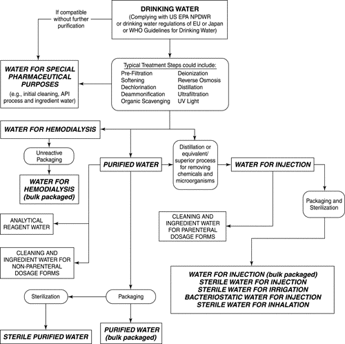


![[PPT PDF] Pharmaceutical Water System Validation - IDENTIFICATION OF MICROORGANISMS](https://pharmawiki.in/wp-content/uploads/2017/11/PPT-PDF-Pharmaceutical-Water-System-Validation-IDENTIFICATION-OF-MICROORGANISMS.jpg)